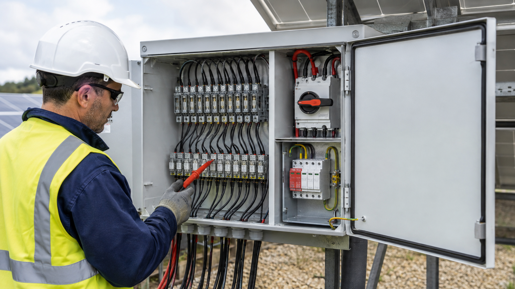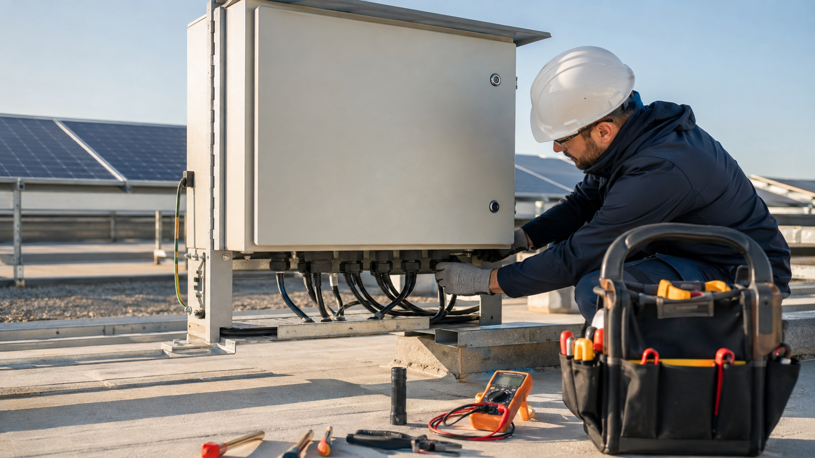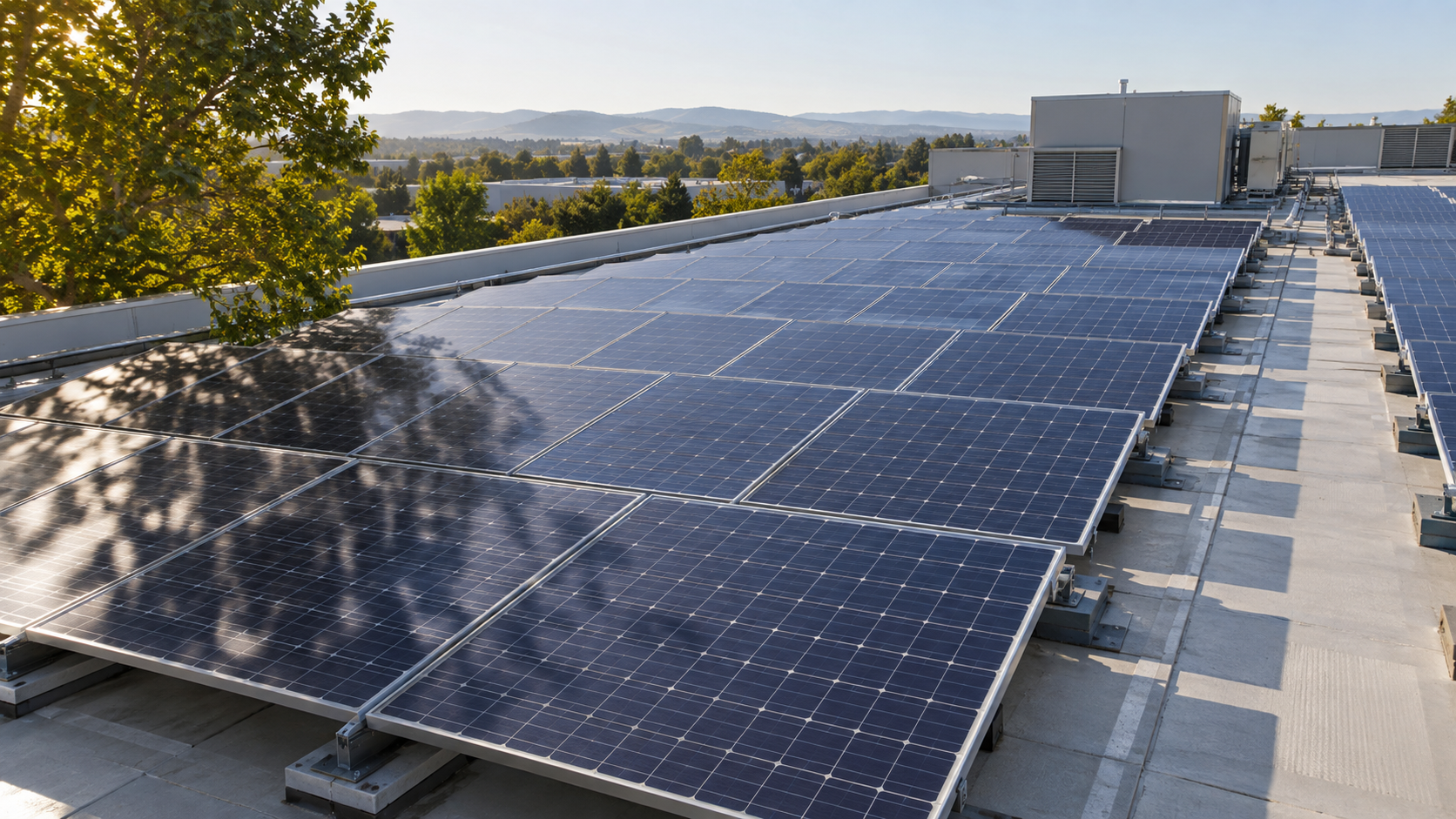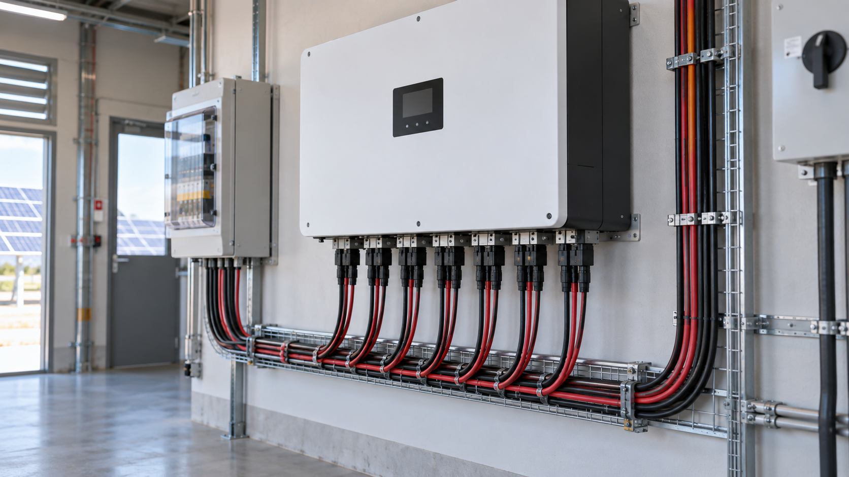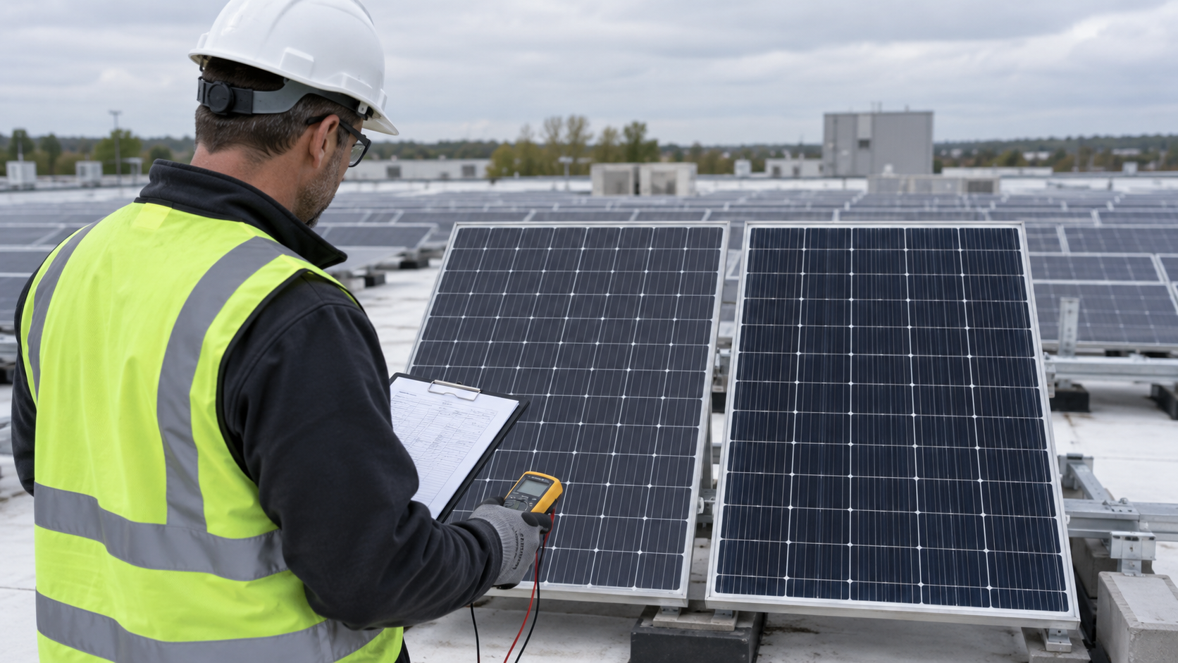
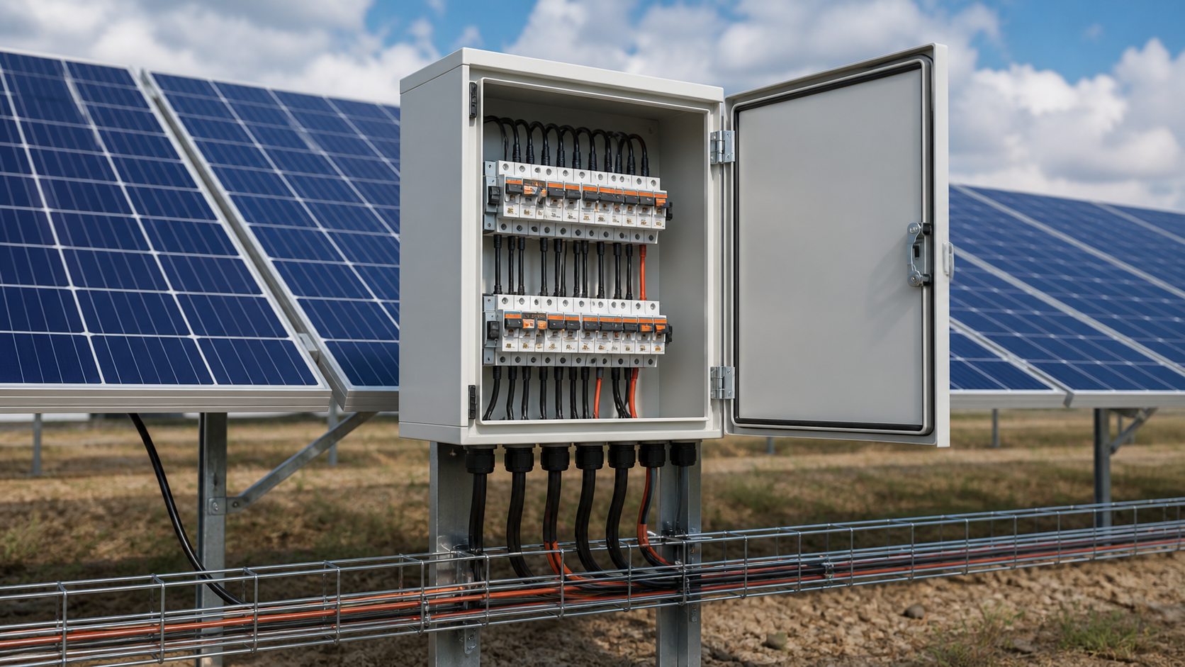
Engineering review scene with an open electrical control cabinet

Solar PV Insights

Technical guidance for PV combiner equipment, AC collection, grid connection and project-ready solar balance-of-system decisions.

Insights categorySolar PV

Project-buyer guidance curated around a specific engineering decision.

Showing 4960 of 103 published guides.

Every guide remains available through the numbered topic pages and its own permanent article URL.

PV combiner engineering context for PV Combiner Box Installation Step by Step

Solar PV

PV Combiner Box Installation Step by Step

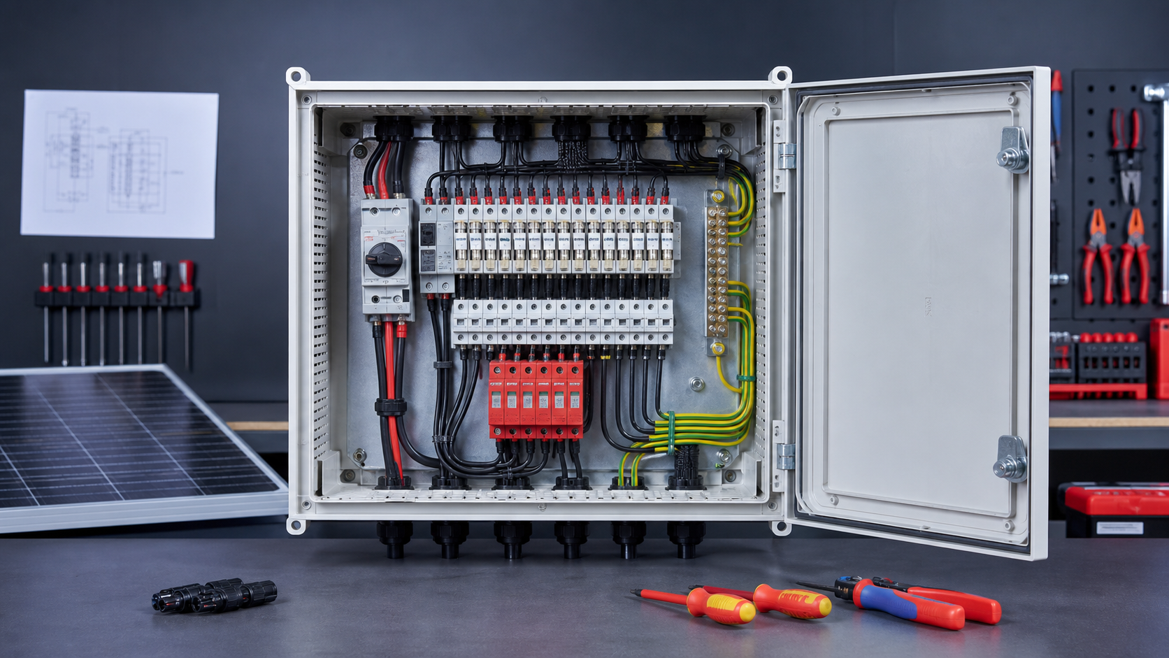
A PV combiner box sits between the module strings and the inverter or grid-connected cabinet, gathering the DC feeds and providing per-string protection. Correct installation is what makes that protection reliable for the full service life of the plant. This guide walks through the installation sequence used on utility-scale and commercial rooftop sites, from pre-installation inspection through to energisation. NEUTRON supplies the combiner box and DC protection equipment; the inverter and battery systems are provided by other parties on the project.
PV combiner engineering context for Preventing Reverse Polarity in Combiner Box Wiring

Solar PV

Preventing Reverse Polarity in Combiner Box Wiring

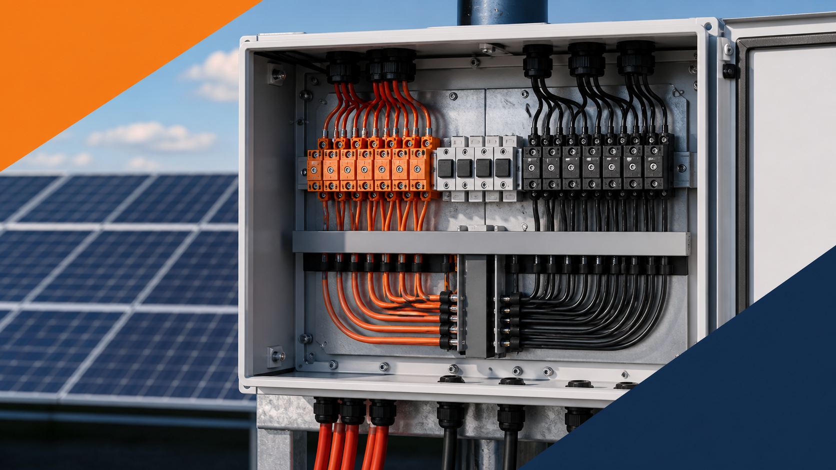
Reverse polarity happens when a PV string is connected with its positive and negative swapped at the combiner box. Instead of adding to the array output, that string subtracts from it, and the mismatch can stress the busbar and protection. Because modules deliver current only one way, a reversed string simply does not contribute — and can mask a fault that later appears as a hot, degraded connection. This guide sets out how NEUTRON-built combiner boxes and field practice prevent it. The inverter and battery systems are supplied by other parties.

PV combiner engineering context for PV Combiner Box Wiring Diagram Explained

Solar PV

PV Combiner Box Wiring Diagram Explained

A wiring diagram is the map that turns a metal enclosure full of terminals into a safe, testable assembly. For a PV combiner box it shows how each module string enters, where it is protected, how the protected feeds combine, and where the surge protection and earth bonds connect. Reading it correctly is the first step before any conductor is landed. NEUTRON designs combiner boxes and the DC protection chain; the inverter and battery systems shown downstream are supplied by other parties.

PV combiner engineering context for PV Combiner Box Common Faults and Troubleshooting Guide

Solar PV

PV Combiner Box Common Faults and Troubleshooting Guide

A PV combiner box sits between the string array and the inverter, collecting DC feeds, protecting each string and passing a clean output to the grid-connected cabinet. Because it carries the full array current and lives outdoors, it is exposed to heat, humidity, lightning transients and constant thermal cycling. Knowing which faults appear most often — and how to read their symptoms — is the difference between a ten-minute fix and a prolonged outage. This guide walks through the eight fault modes NEUTRON field teams see most, then a practical diagnosis and maintenance routine.

PV combiner engineering context for PV Combiner Box Preventive Maintenance Checklist Guide

Solar PV

PV Combiner Box Preventive Maintenance Checklist Guide

A PV combiner box asks for little attention and repays it many times over. Left unmaintained, the same box that protects the array becomes the array's weakest point — a loose terminal, a failed surge protector or a blocked vent can take a string or a whole output offline. A preventive maintenance routine turns those risks into a short, scheduled checklist. This guide sets out the eight steps NEUTRON recommends for keeping combiner boxes inside their design envelope.

PV engineering context for Solar Panel Dimensions and Weight: A Practical Sizing Reference

Solar PV

Solar Panel Dimensions and Weight: A Practical Sizing Reference

Module dimensions and mass look like a mechanical detail, yet they are the first numbers an electrical engineer needs before any balance of system (BOS) can be specified. Panel footprint sets the row pitch, the cable run length between the array and the enclosure, and the amount of free wall or rail space available for a combiner box. Panel mass sets the structural load the roof or the ground frame must carry. NEUTRON does not manufacture modules. As a supplier of PV combiner equipment, DC control and protection assemblies and low-voltage distribution gear, our starting input is always the module datasheet: dimensions, weight, cell count and electrical ratings. This reference explains what the common sizes are and how they translate into practical decisions about string layout, conductor length and enclosure placement.

PV engineering context for Cloud-Edge Effect: Why Solar Panels Exceed Rated Power

Solar PV

Cloud-Edge Effect: Why Solar Panels Exceed Rated Power

Anyone who watches a photovoltaic monitoring screen on a partly cloudy day sees something that appears impossible: for a few seconds the array reports more power than the modules are rated to produce. This is the cloud-edge effect, and it is a genuine optical and electrical phenomenon rather than a measurement error. It matters because protection equipment sized for average conditions will be tested by these brief peaks. For NEUTRON, which supplies PV combiner equipment, DC control and protection assemblies and busbar and distribution components, over-irradiance events are a sizing input. Fuses, busbars, isolators and conductors have to tolerate the peak rather than the mean. This article explains the mechanism and then works through what margin the balance of system actually needs.

PV engineering context for Solar Panel Shading: How It Affects Your String

Solar PV

Solar Panel Shading: How It Affects Your String

Shading is the most misunderstood loss mechanism in photovoltaic design. Owners expect that covering a tenth of an array costs a tenth of the output, and are surprised when a single shaded module drags an entire series string down by a much larger margin. The reason is electrical, not optical: modules in series share one current path, and the weakest link sets the current for everyone. As a supplier of balance-of-system equipment — combiner boxes, direct-current control and protection, and low-voltage switchgear — NEUTRON is concerned with what shading does downstream of the modules: how it changes string current, why it creates thermal stress inside the module, and how the protection and monitoring at the combining point should be specified to cope with it.

PV engineering context for Solar Panel Datasheet: Every Spec Explained (Voc, Vmpp, Isc)

Solar PV

Solar Panel Datasheet: Every Spec Explained (Voc, Vmpp, Isc)

A module datasheet is a two-page document that decides most of the electrical design behind an array. String length, conductor cross-section, fuse rating, isolation device rating, busbar capacity and enclosure requirements all trace back to a handful of numbers printed on it. Read the datasheet correctly and the balance-of-system specification follows almost automatically; misread one figure and the error propagates through the entire installation. NEUTRON supplies the equipment those numbers feed into — combiner boxes, direct-current control and protection, busbar components and low-voltage switchgear — and the most common cause of a mis-specified assembly is a datasheet value taken at face value without the temperature and irradiance context that goes with it. This guide walks through each specification and states plainly what it is used for.

PV engineering context for Distributing Panels Across MPPT Inputs: A Practical Guide

Solar PV

Distributing Panels Across MPPT Inputs: A Practical Guide

Modern inverters offer multiple independent tracking inputs, and how you allocate strings between them has a direct effect on annual yield. Get it right and every roof plane operates at its own optimum. Get it wrong and a well-built array quietly loses several percent every day, with no fault indication anywhere in the system. NEUTRON supplies the array-side equipment that sits between the modules and those tracking inputs — combiner boxes, direct-current control and protection, and busbar components. From that position, the distribution decision is not abstract: it determines how many protected inputs are needed, how the enclosure is partitioned, and how many separate output feeds run to the inverter. This guide covers the electrical logic and the practical layout that follows from it.