
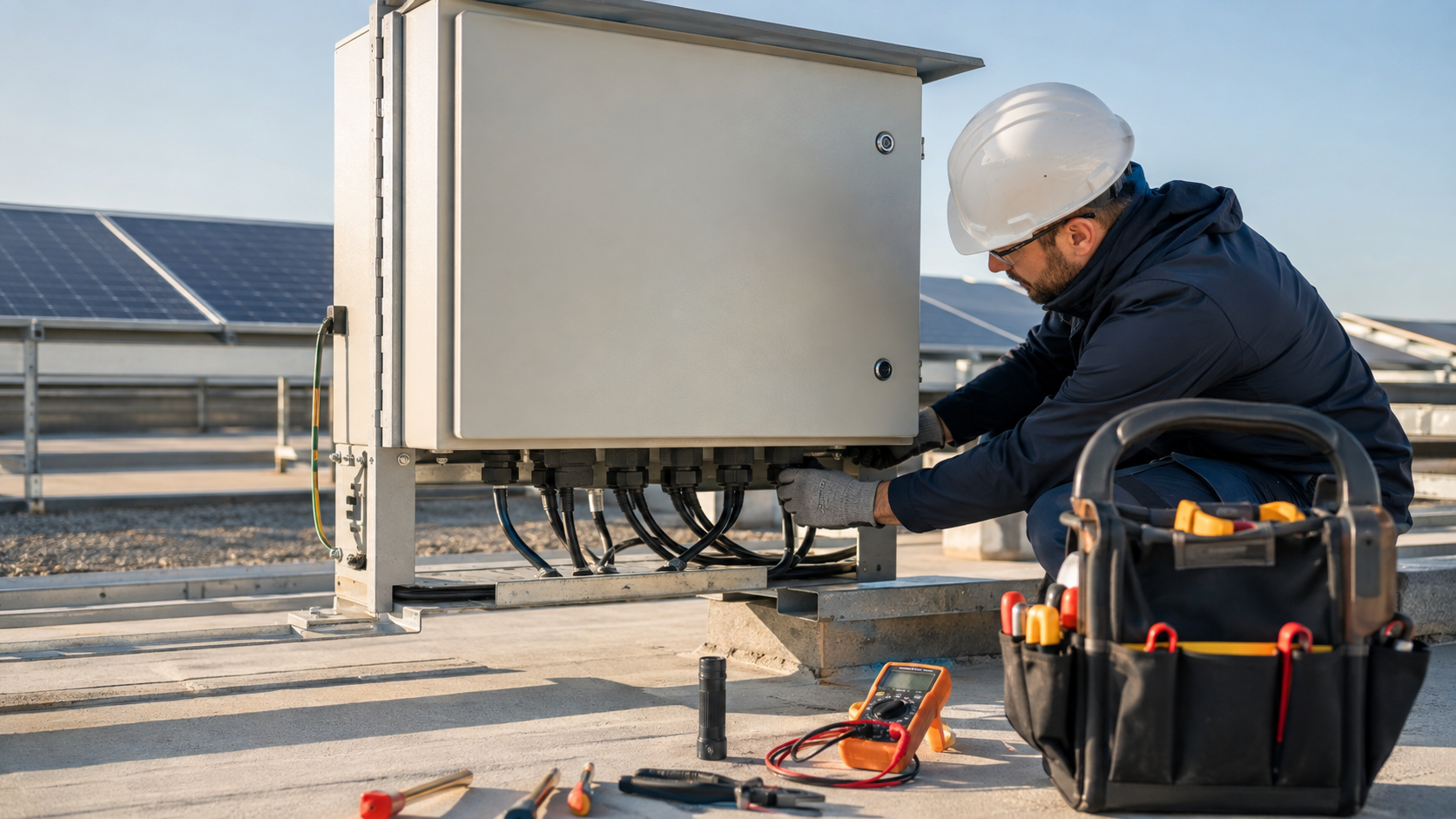
Inspection frequency
How often to inspect depends on the site. A mild rooftop array can run on a six-month visual and a yearly thermal scan; a coastal or desert plant earns a quarterly visit because corrosion, dust and heat accelerate every fault mode. Set the calendar from the site class, then keep it.
- Temperate sites: visual every 6 months, thermal yearly.
- Coastal or desert sites: visual quarterly, thermal every 6 months.
- After any major storm or lightning event: inspect on return.
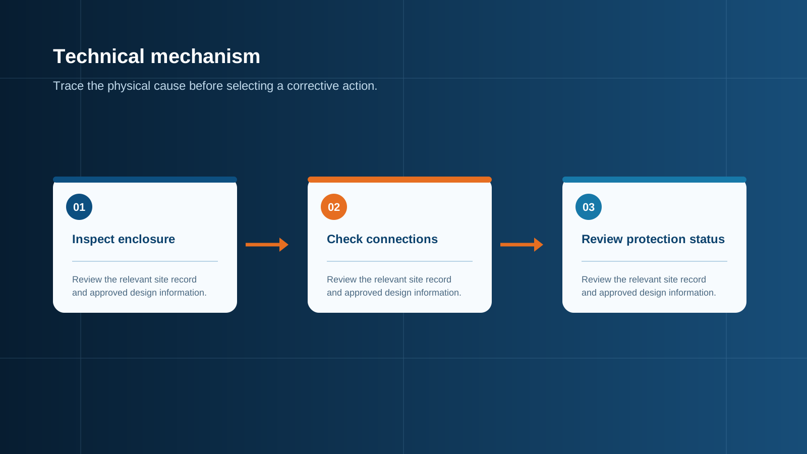
Technical diagram shown at a readable responsive scale.
Visual and seal check
Most faults announce themselves visually before they trip. Open the enclosure (under lock-out), look for discolouration, moisture, insect nests or cracked parts, and confirm the seals and cable glands still exclude water and dust. A failed seal is the start of corrosion and a ground fault.
- Check door seals, gaskets and cable glands for integrity.
- Look for moisture, condensation or corrosion inside.
- Confirm the enclosure rating still matches the site.
Torque re-tightening
Thermal cycling loosens terminals over time, so re-torquing is the single highest-value task. Use a calibrated tool, apply the manufacturer value for each conductor, and record it. A terminal checked and logged is a terminal that will not start a fire.
- Re-torque every power terminal to the specified value.
- Use a calibrated tool, not a fixed wrench.
- Record torque, tool ID and date on the label.
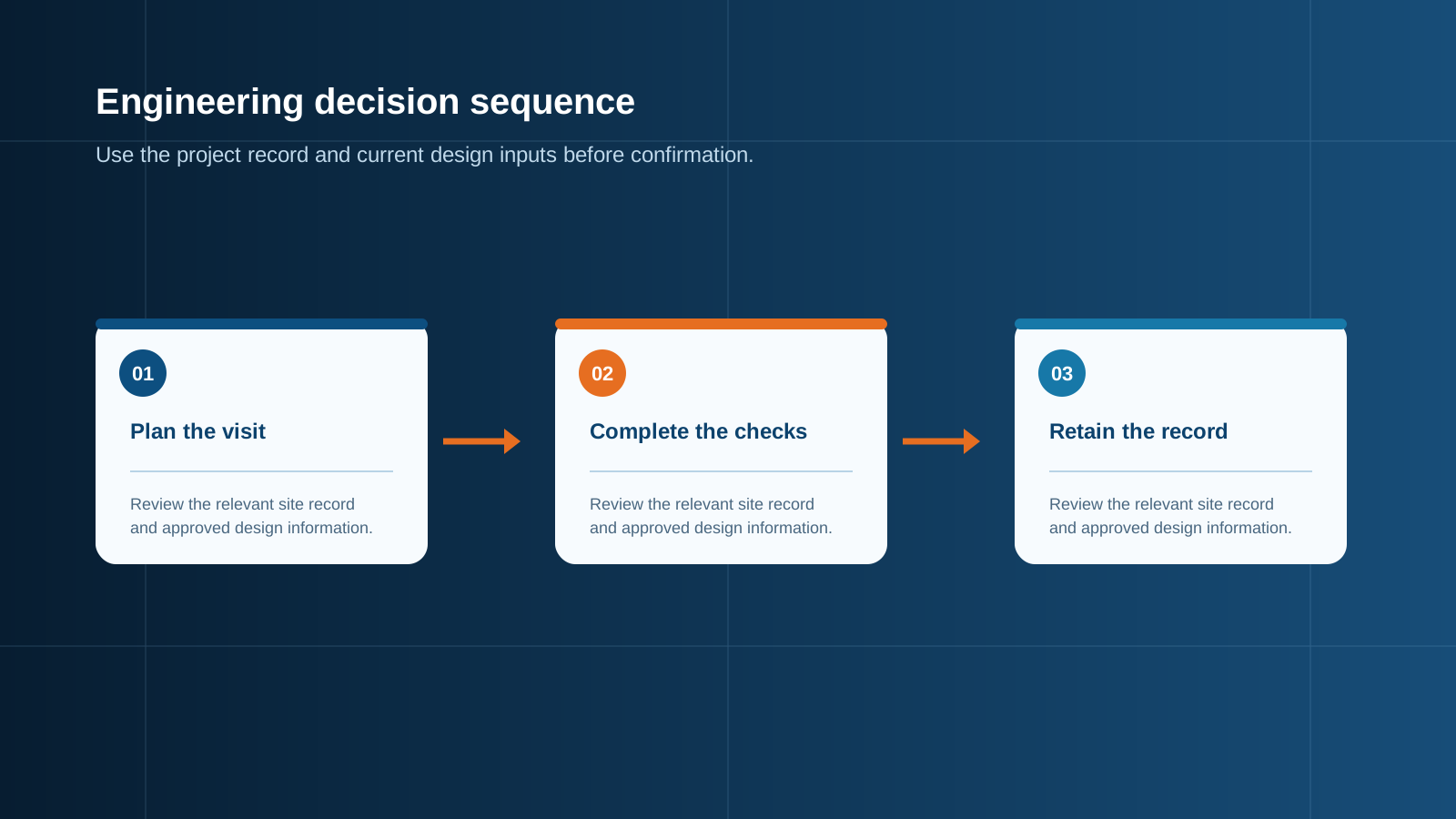
Technical diagram shown at a readable responsive scale.
SPD status
The surge protector is a consumable: it sacrifices itself to lightning and switching transients. Check the visual window and the remote alarm at every visit, and replace any module at end-of-life with the same Uc and Up envelope. A failed SPD left in circuit is a heating and protection risk.
- Read the green/red status window.
- Confirm the remote signal reaches the platform.
- Replace on confirmed failure with the matching rating.
Thermal imaging
A thermal camera under load finds the faults a visual check cannot: a heating terminal, an overloaded busbar, a degraded device. Scan each box at rated current and compare terminals on the same busbar; a hotspot that grows between visits is the work list for the next shutdown.
- Scan under rated load for a true reading.
- Compare terminals and busbar for balance.
- Trend hotspot temperatures across visits.
Cleaning
Dust, pollen and salt film raise enclosure temperature and can bridge insulation inside. A careful clean of the exterior and, where safe, the interior keeps ventilation clear and surfaces dry. Use only methods that cannot drive moisture into the busbar zone.
- Remove dust from vents, fins and the enclosure surface.
- Clean interior only under lock-out and with dry methods.
- Keep the solar-exposed face reflective where needed.
Comms check
A combiner box that reports nothing hides every other fault. Verify the logger has auxiliary power, the bus cable is sound, and the station ID and data are reaching the portal. A comms loss is a protection blind spot and must be cleared before sign-off.
- Verify auxiliary supply at the logger.
- Check the bus cable shield and termination.
- Confirm data and alarms reach the monitoring platform.
Spare parts
Downtime is shortest when the right spare sits on the shelf. Keep a small kit of the wear items — gPV fuses, SPD modules, a breaker, terminal blocks and seals — matched to the exact box model. NEUTRON documents the spare-part list as part of the project handover so a fault becomes a swap, not a wait.
- Stock gPV fuses and SPD modules by rating.
- Keep a breaker, terminal block and seal kit on site.
- Match every spare to the installed model and version.
This is general technical guidance. Confirm final ratings, protection coordination, installation and applicable local requirements against current standards, manufacturer documentation and the approved project design.
Frequently asked questions
How often should a combiner box be maintained?
It follows the site class. Temperate arrays suit a six-month visual and a yearly thermal scan; coastal or desert plants earn a quarterly visual and a six-month thermal scan, plus an inspection after any major storm.
What should I check during maintenance?
Inspect seals and glands, re-torque terminals, check SPD status, thermal-image the loaded box, clean vents and surfaces, verify comms, and confirm spare parts. Each step targets a specific fault mode.
Why re-torque terminals?
Thermal cycling loosens terminals over time, raising contact resistance and heat. Re-torquing with a calibrated tool to the manufacturer value is the single highest-value task and prevents terminal overheating.
Why use thermal imaging?
A thermal camera under load finds heating terminals, overloaded busbars and degraded devices that a visual check misses. Comparing hotspots across visits shows which joints are drifting toward failure.
Which spare parts should I keep?
Keep gPV fuses and SPD modules by rating, plus a breaker, terminal block and seal kit matched to the exact box model, so a fault becomes a swap rather than a long wait for parts.
Discuss your PV combiner requirement
Share the system voltage, string count, inverter interface and installation environment. NEUTRON can review the equipment configuration around your project documentation.
Discuss a projectContinue learning
Explore related technical guidance in Solar PV.
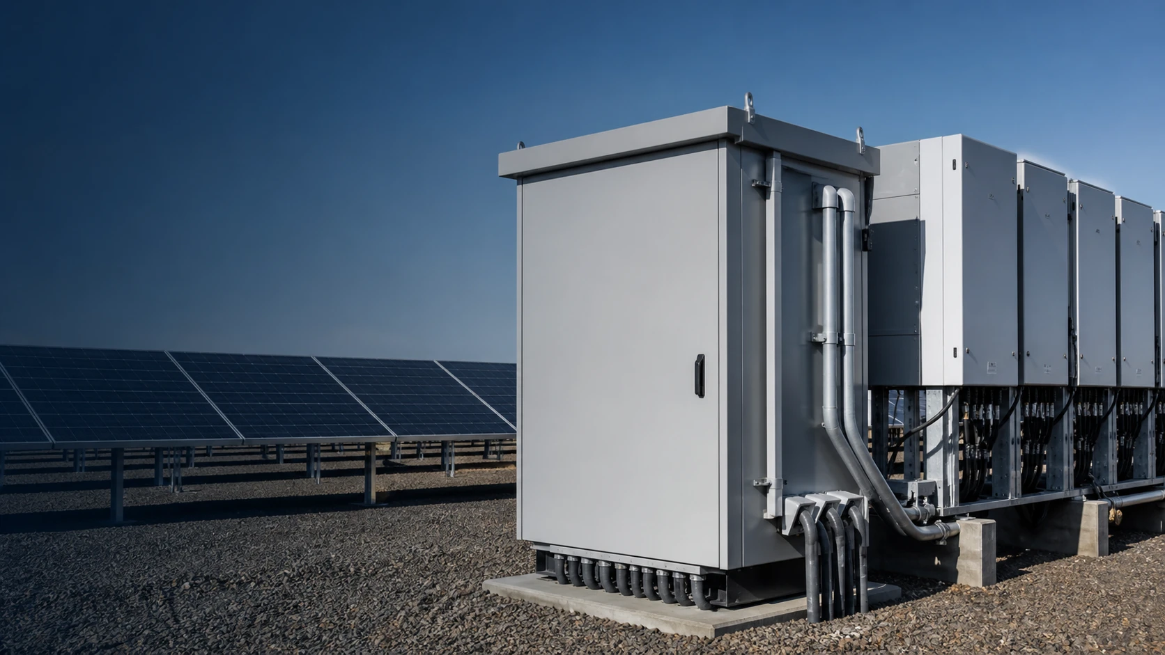

Published from the approved Period 09 source package. Technical values and final design decisions must be verified against the current applicable standard, manufacturer documentation and approved project design.