
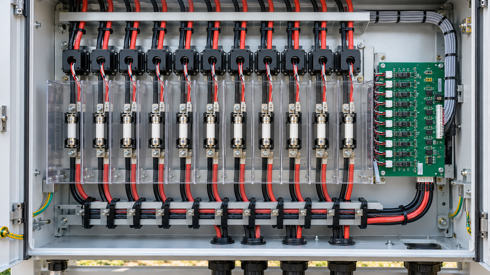
Choose what each channel must reveal
An inverter total may conceal a change in one of many parallel strings. Individual channels help localize an interruption or persistent deviation when sunlight and plant operation permit a useful comparison. Monitoring supports diagnosis and maintenance prioritization; it cannot uniquely identify a failed module from current alone.
Define the physical string ID, expected operating-current range, resolution, sampling interval and required alarm behavior before selecting electronics. A channel must remain traceable to the as-built array and fuse position after replacement or rewiring.
Select sensors that can measure steady DC
Hall-effect transducers and suitably designed shunt measurement circuits can measure DC. An ordinary transformer-type AC current sensor does not measure steady DC. A Hall device may sense a conductor through an aperture or use an integrated current path, so installation details must match the exact sensor design.
Check offset drift, temperature behavior, saturation, polarity, bandwidth and rated current range. A galvanically isolated output is useful, but the specific working voltage, insulation category, creepage, clearance and assembly environment determine whether the complete measurement boundary suits the PV system.
Keep the signal chain and protection chain distinct
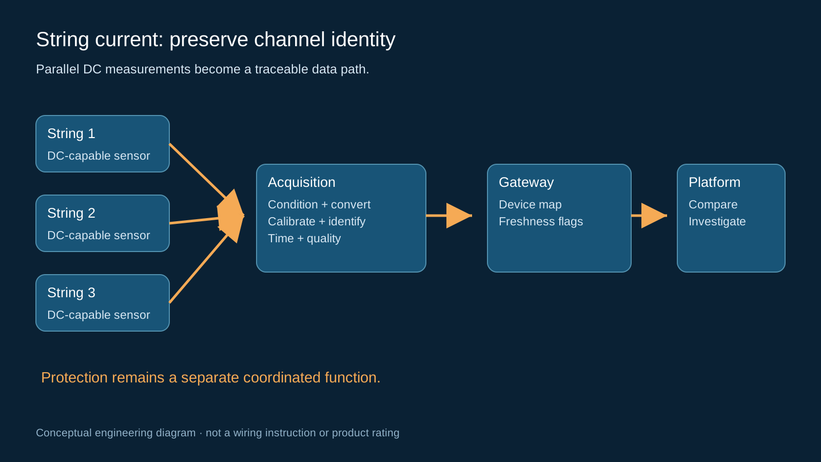
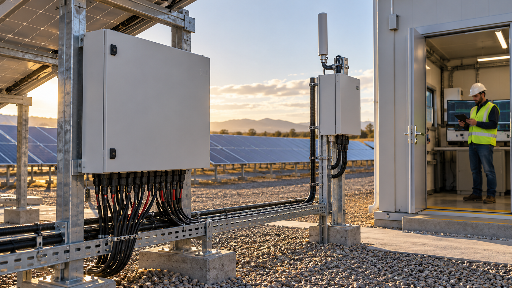
The signal chain runs from each sensor through conditioning and conversion to a controller, then a field interface and gateway. Fuses, switching and other protective devices retain their own coordinated functions. A general current sensor and software threshold do not become a certified protective system merely because an alarm is available.
For a shunt-based circuit, assess the shunt burden, thermal dissipation and fault behavior along with the isolated amplifier or converter. Do not connect a high-voltage measurement point directly to a low-voltage controller or assume that a nominally low signal amplitude establishes safe isolation.
Technical diagram shown at a readable responsive scale.
Control offset, filtering and calibration
The converter resolution is only one part of measurement quality. Sensor offset, gain error, reference stability, channel crosstalk and temperature drift can dominate, especially near low current. Document the usable range and uncertainty rather than advertising converter bit count as system accuracy.
Calibrate channel gain and offset with a suitable reference and retain the method and conditions. Filtering should reduce interference without hiding a relevant event. Record whether transmitted values are instantaneous, averaged or accumulated so upstream comparison uses compatible quantities.
Compare like strings at compatible times
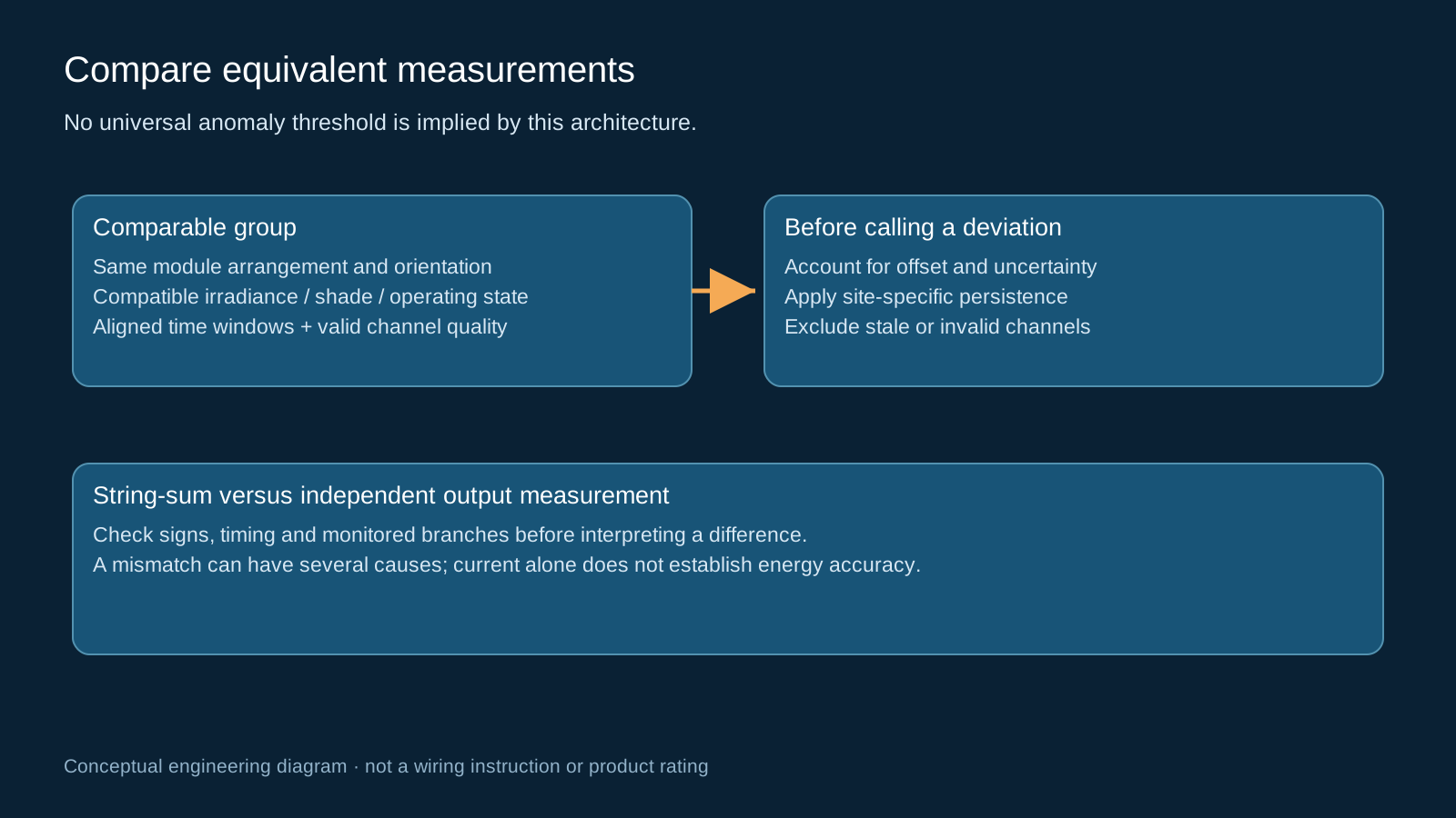
Compare strings with similar module count, orientation, irradiance and shading conditions. Align measurement intervals sufficiently for the intended diagnostic task and exclude stale or invalid channels. Irradiance changes can make a slow sequential scan look like an electrical mismatch.
Use project-specific persistence and deviation rules. A fixed percentage threshold is not equally valid for all array layouts or light levels. Current measurements support anomaly detection; they do not by themselves establish energy accuracy, a complete performance ratio or a particular degradation mechanism.
Technical diagram shown at a readable responsive scale.
Reconcile string sum and output current
An independently measured output current can be compared with the sum of individual channels when both use compatible timing and sign conventions. Include each measurement uncertainty and identify intentionally unmonitored branches before interpreting a difference.
A discrepancy may indicate mapping, polarity, sensor drift, timing or wiring issues. It does not automatically prove an unmonitored bypass. Likewise, current plus one busbar-temperature reading does not certify the assembly continuous-current or temperature-rise rating.
Carry identity and quality to the gateway
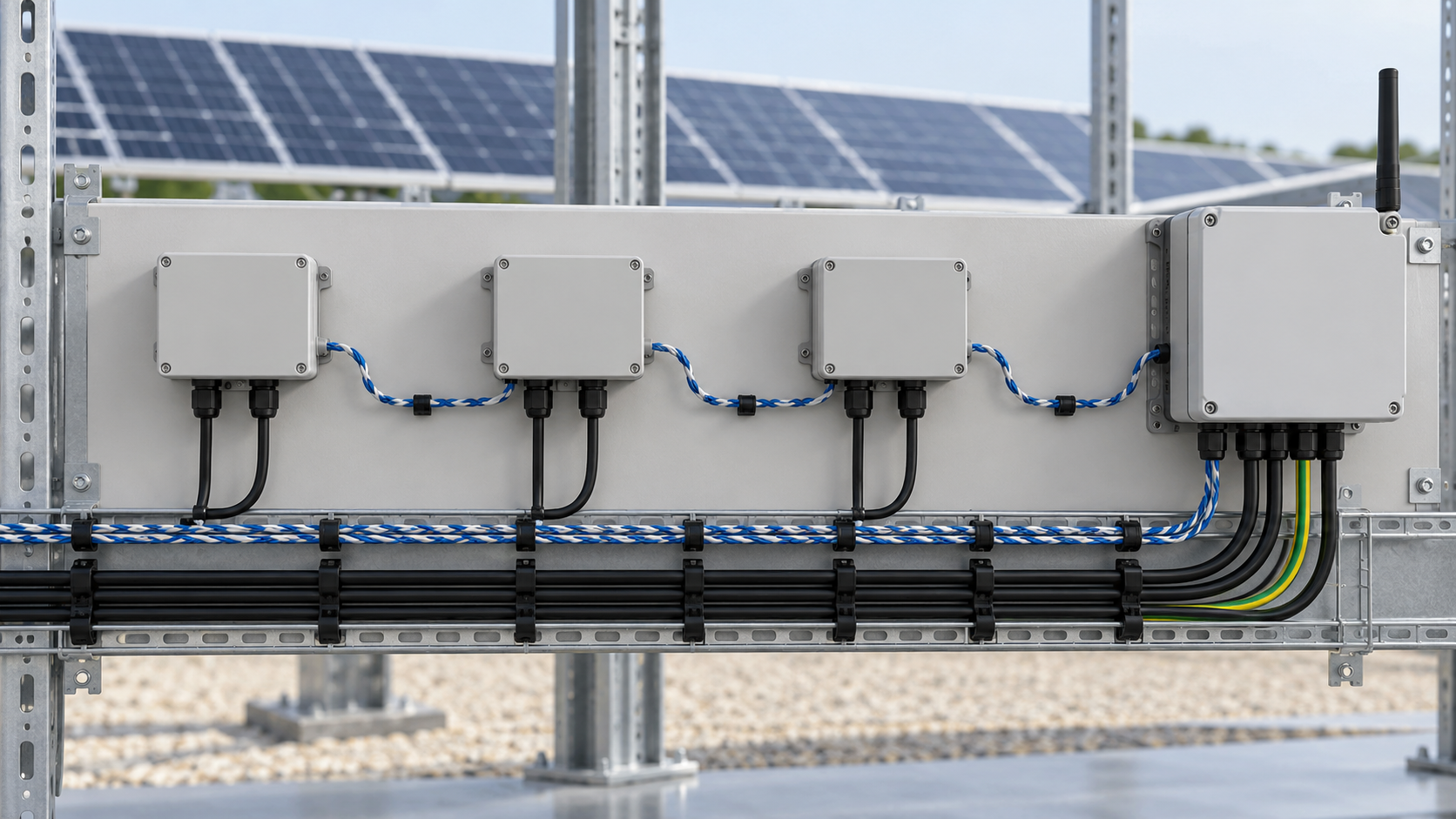
Expose channel values, units, scale, sensor or controller diagnostics and data-age information through a documented interface. RS485 with Modbus RTU is one option; the gateway must decode the actual device map and maintain a quality state alongside the value.
If the device supplies no timestamp, record the polling time and distinguish it from the original measurement time. Treat disconnected sensors, frozen values, power loss and communication failure as separate diagnostic conditions rather than converting them all to zero current.
Validate the architecture during commissioning
Prove channel-to-string identity, polarity and scaling with a safe controlled test and a suitable reference. Check normal operation, low-light gating, a simulated sensor fault, communication loss and restoration. Keep actual test records with configuration backups.
- Document sensor range and complete insulation requirements.
- Record reference instrument, conditions and channel calibration results.
- Verify alarm persistence and comparison groups against the actual array.
- Use qualified inspection to confirm electrical causes after remote localization.
General engineering guidance, not a project design, product certificate or safe-work procedure. Verify ratings, isolation, protection coordination, software behavior and local requirements against the exact equipment documentation and approved project design.
Frequently asked questions
Can an ordinary CT measure PV string DC?
An ordinary AC transformer-type CT cannot measure steady DC. Use a DC-capable method such as an appropriate Hall transducer or a suitably isolated shunt circuit.
Does a Hall sensor automatically suit a 1500 V combiner?
No. Review its specified working voltage and insulation limits, spacing and installation within the complete assembly. A nominal isolated output alone is insufficient.
Can low current identify the failed component?
It can help locate an abnormal string but cannot uniquely distinguish shading, an open circuit, sensor error or a particular component fault without other evidence.
Why compare the string sum with output current?
It is an integrity check when timing, polarity, monitored branches and uncertainty are understood. A difference is a prompt to investigate, not proof of one wiring fault.
What must travel with each current reading?
A physical channel identity, units and scaling, measurement or polling time, and quality or diagnostic state sufficient to distinguish valid data from stale or failed measurements.
Review your combiner monitoring requirement
Share the DC system voltage, string count, sensor and alarm requirements, existing gateway interface and installation environment so the proposed configuration can be reviewed against the project documentation.
Discuss a projectContinue learning
Explore related technical guidance in Solar PV.
References describe general technology and documented scope. They do not certify a NEUTRON configuration or establish measured performance at a customer installation.