
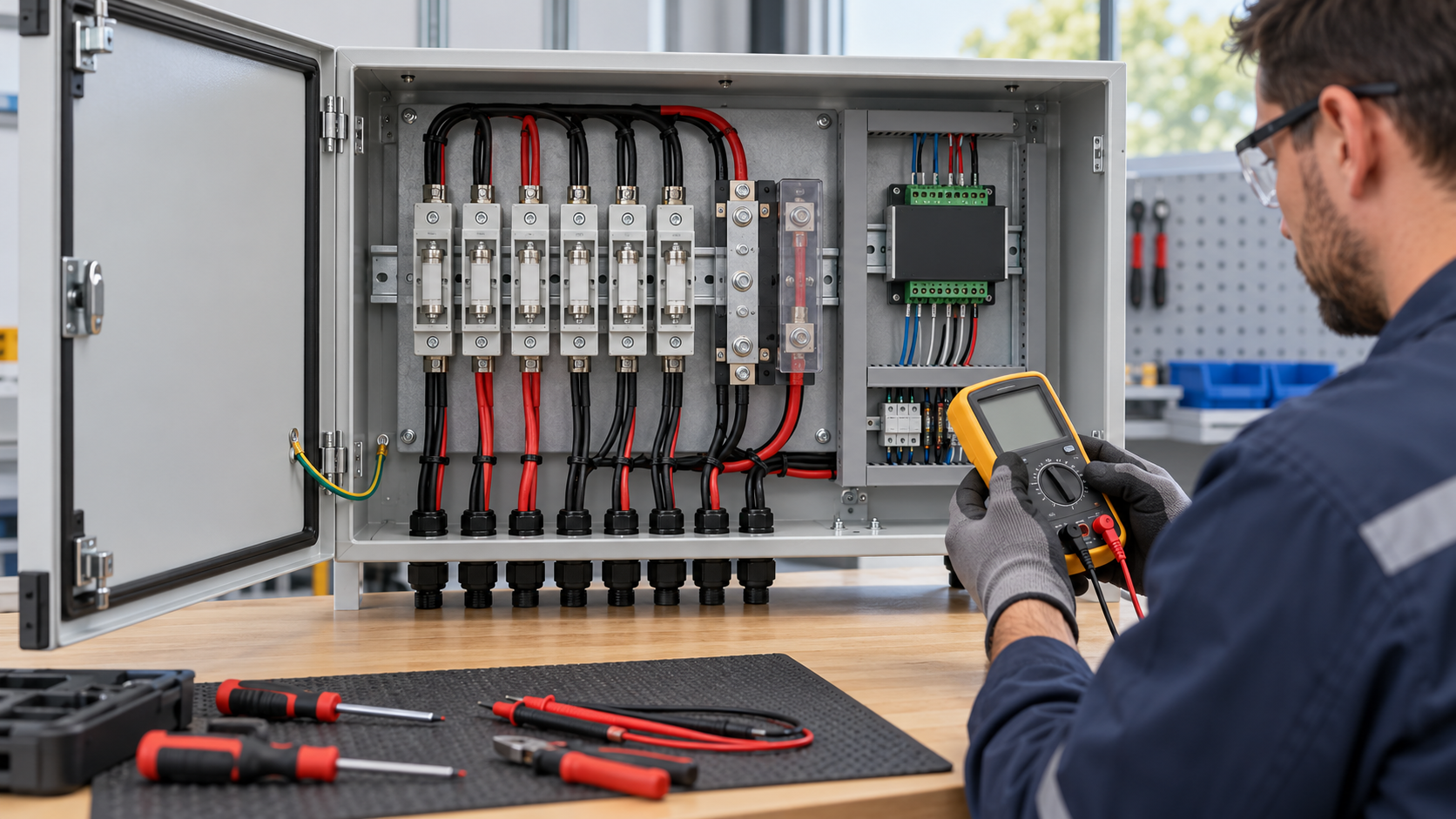
Why remote fuse alarms need context
A blown string fuse can reduce production without stopping the inverter. Remote reporting helps an operator locate the affected input earlier, especially where aggregate inverter current masks a single-string change. The benefit depends on detection coverage, communications and the maintenance response; it is not an automatic yield or warranty guarantee.
Separate a suspected loss of string current from a confirmed fuse indication. A disconnected connector, open conductor, inverter stop, low irradiance or failed sensor can produce a similar reading. The event should carry its evidence and confidence rather than declare an unsupported root cause.
Fuse indication and current are different signals
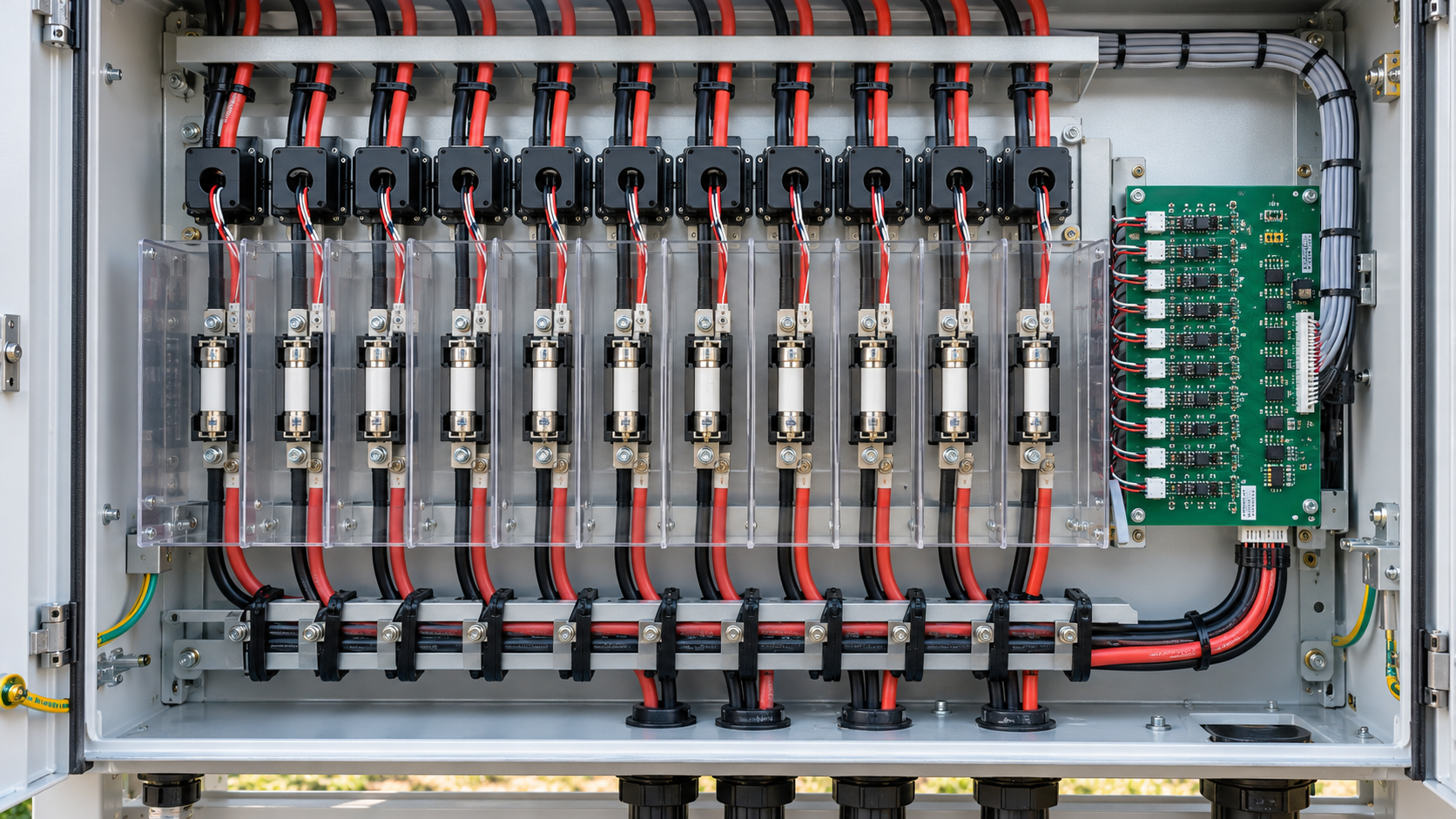
A current channel detects whether measured current is below an expected operating range. It cannot, by itself, distinguish a blown fuse from every other open-circuit condition. A purpose-designed fuse monitor may sense voltage across the fuse, read a compatible indicator, or use an auxiliary mechanism. Each method has operating-voltage, polarity and test limitations.
Specify the exact fuse, holder and indication accessory together. Verify the required energization condition, monitor supply, detection threshold and channel isolation against the manufacturer documentation. A status output does not prove that both sides of a fuse are safe to touch.
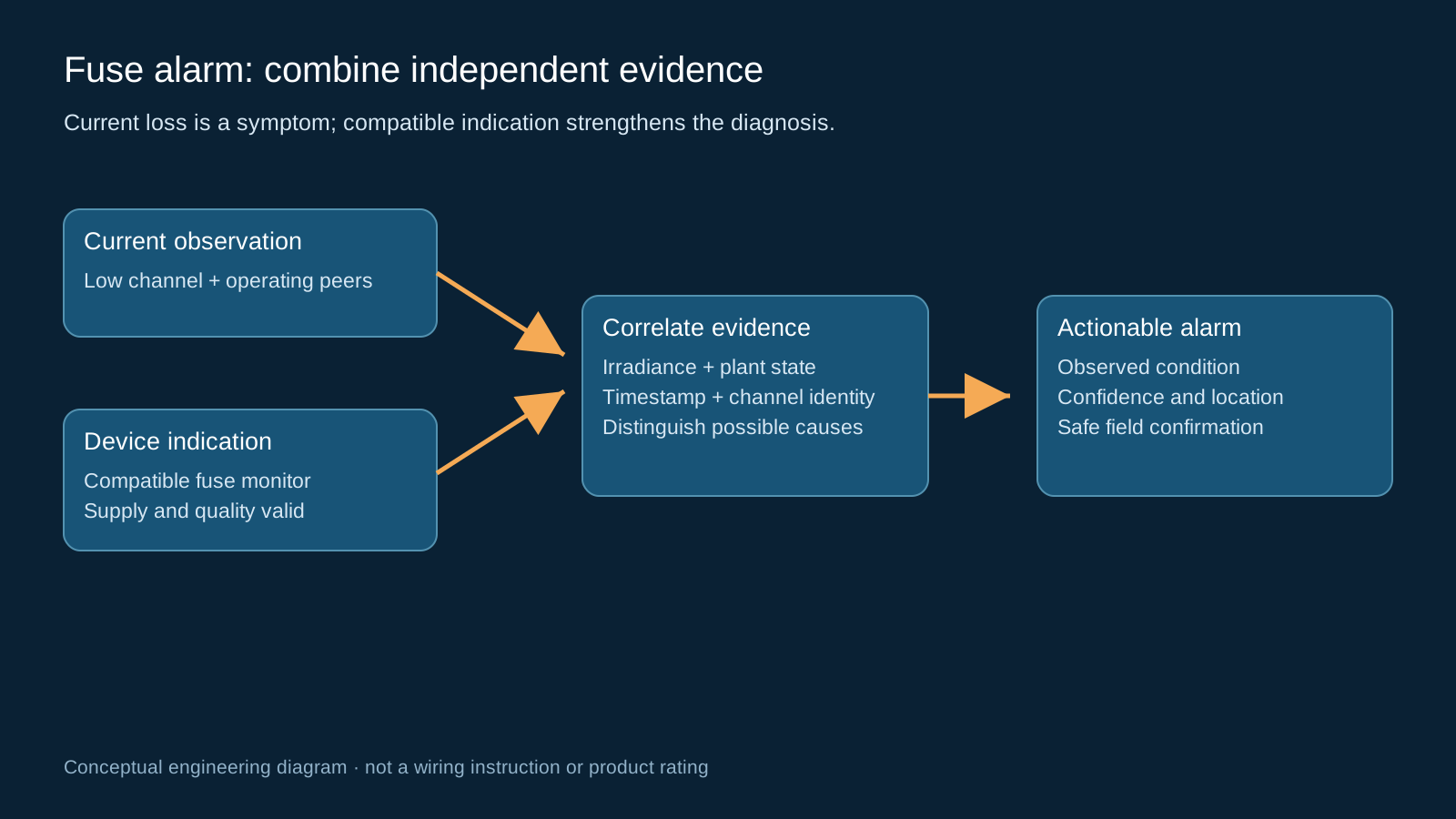
Technical diagram shown at a readable responsive scale.
Dry contacts and digital telemetry
A dry contact is a potential-free switching interface within its rated limits. It does not generate the external sensing voltage and does not make an arbitrary connected circuit safe. Match contact voltage/current ratings, input wetting requirements, separation and wiring to the receiving input.
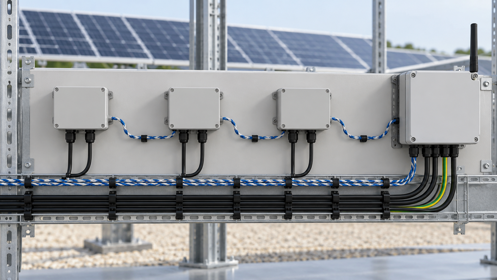
Decide whether a common contact reports one box-wide fault or individual channels are available. For Modbus telemetry, document unit ID, register address, bit meaning, normal state, alarm state and communication-failure behavior. The protocol does not guarantee that every device exposes a fuse-specific register.
Qualify alarms before dispatch
Enable current-based comparison only when irradiance and plant operating state support useful current. Compare equivalent strings with compatible orientation, module count and exposure, and use a persistence interval suited to sampling and shading behavior. Do not apply a universal zero-current threshold to every site.
- Treat stale readings, sensor faults and lost communications as separate quality events.
- Cross-check current loss with other strings, inverter status and available fuse indication.
- Record box and channel identity, event time, last-good sample and the evidence used.
Interpret the evidence
The alarm message should tell the operator what is observed and what remains to be checked.
| Observation | Working interpretation | Next check |
|---|---|---|
| One current channel low; peers operating | Suspect string interruption or sensor issue | Check data quality and compatible fuse indication |
| All channels low together | Possible low light or plant stop | Check irradiance, inverter and supply state |
| Fuse indication asserted with fresh data | Fuse-related event within monitor limitations | Qualified inspection and cause investigation |
| Old timestamp or communication timeout | Measurement unavailable | Restore telemetry before current diagnosis |
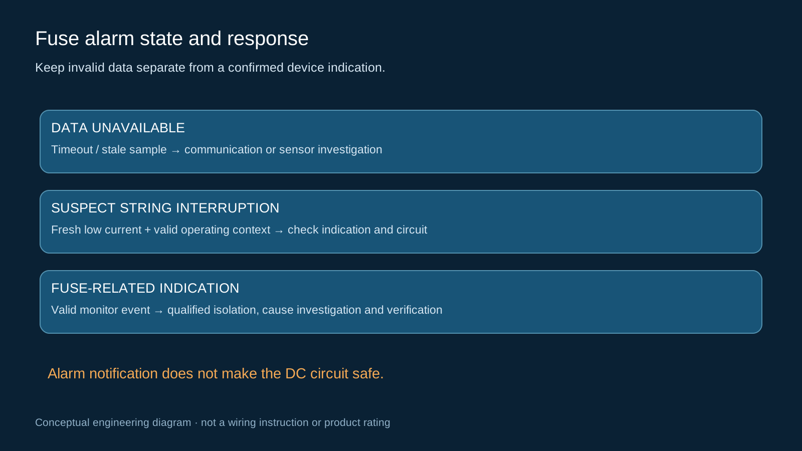
Technical diagram shown at a readable responsive scale.
Maintain protection and safe isolation
The monitoring circuit supplements the existing protection design. It does not replace the gPV fuse, coordinated protection, a DC-rated switching device or the approved isolation procedure. A fuse holder must not be opened under load unless its manufacturer explicitly rates that operation.
Qualified personnel should follow the approved shutdown, isolation and verification procedure, account for PV sources remaining energized in daylight, investigate why the fuse operated, and fit the specified replacement. Repeated replacement without cause analysis can leave an underlying fault unresolved.
Commission the full event path
Prove the input-to-platform mapping with an approved test method before relying on remote dispatch. Use the monitor test function or a safe controlled simulation rather than deliberately creating a live DC fault. Verify that channel labels match the physical fuse layout.
Test normal state, alarm state, broken signal wiring where supported, monitor power loss, communication timeout, acknowledgement and recovery. Confirm which events latch and which clear automatically, then retain the actual results with the as-built documentation.
Close the maintenance loop
A useful work order includes the physical location, observed signals, safety constraints and likely checks. After repair, confirm fresh measurements under valid operating conditions and check that both local indication and platform alarm return to the expected state.
Record the diagnosed cause, replacement part and test result. Restored telemetry is evidence of communication recovery; restored current supports operational recovery but does not independently certify the complete assembly or establish the original fault cause.
General engineering guidance, not a project design, product certificate or safe-work procedure. Verify ratings, isolation, protection coordination, software behavior and local requirements against the exact equipment documentation and approved project design.
Frequently asked questions
Does zero string current prove a blown fuse?
No. Low light, a plant stop, an open connector or conductor, a sensor problem and stale data can also produce an apparent zero. Use operating context, compatible fuse indication and safe field verification.
What does a dry-contact fuse alarm provide?
It provides a potential-free contact state within specified ratings. The external sensing circuit, isolation requirements and fail behavior must be designed and verified; the contact does not make the connected circuit intrinsically safe.
Can Modbus identify the failed string?
Only if the device register map exposes the relevant per-channel state and the gateway maps it correctly. Some contacts report only a combined box-level alarm.
How are nuisance fuse alarms reduced?
Check irradiance and operating state, compare equivalent strings, use an appropriate persistence interval and separate invalid or stale data from a true measurement.
Can a fuse alarm replace a DC disconnect?
No. Indication is monitoring. Isolation and switching require appropriately rated equipment and the approved safe-work procedure.
Review your combiner monitoring requirement
Share the DC system voltage, string count, sensor and alarm requirements, existing gateway interface and installation environment so the proposed configuration can be reviewed against the project documentation.
Discuss a projectContinue learning
Explore related technical guidance in Solar PV.

References describe general technology and documented scope. They do not certify a NEUTRON configuration or establish measured performance at a customer installation.