
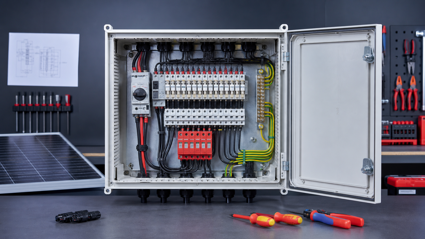
Reading a wiring diagram
Most diagrams follow a left-to-right flow: strings enter on the left, protection sits in the middle, and the combined DC output leaves on the right. Symbols follow IEC conventions, so a rectangle with a line through it is a switch, a triangle is a semiconductor device, and a zig-zag or box with a strike is a surge protective device.
- Identify the system voltage (1000 V or 1500 V DC) and the number of input strings.
- Locate the main DC disconnect and the output busbar before tracing individual strings.
- Confirm the earth and bonding symbols — they are as important as the live conductors.
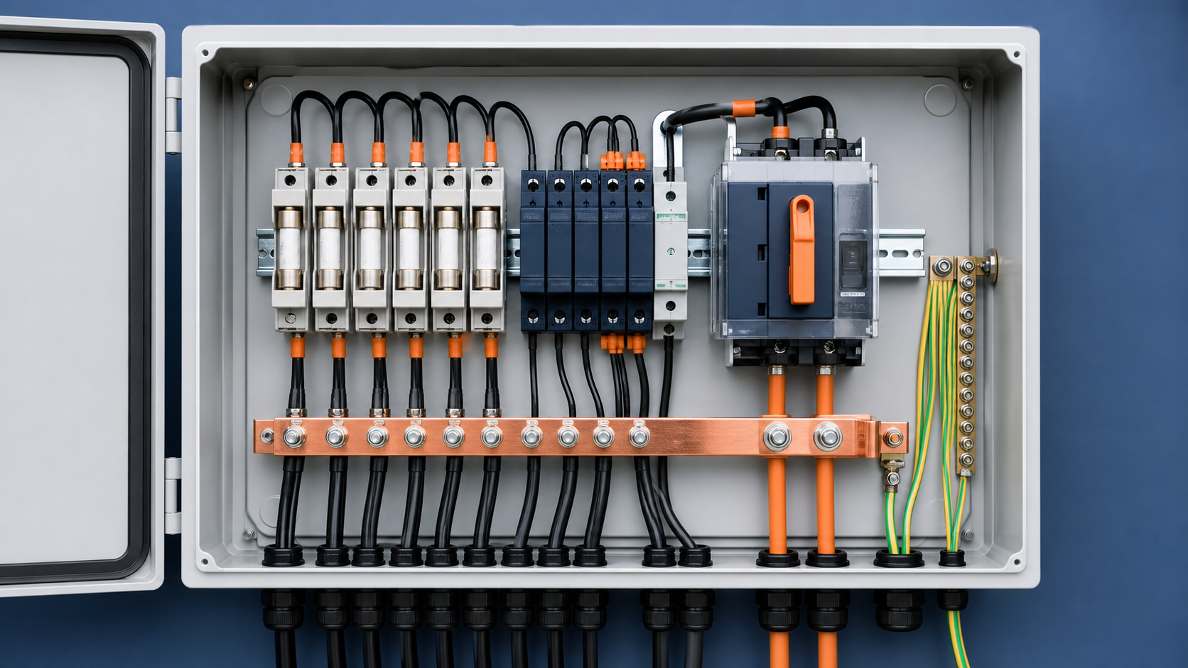
String input side
Each PV string arrives as a positive and a negative conductor through its own cable gland. On the diagram these appear as paired terminals, one per string, usually numbered S1+, S1− through Sn+, Sn−. The input side is where polarity is set, so the diagram and the physical labelling must agree.
- One fused input per string; never parallel two strings onto a single fused path.
- Keep the + and − of a pair adjacent to reduce loop area and induced noise.
- Match the gland size to the cable so the entry remains sealed to the stated IP rating.
Fuse and protection layout
Every string passes through a gPV fuse sized to the string short-circuit current, typically 1.25×Isc per IEC 60269-6. On the diagram the fuse sits immediately after the input terminals, in series with the positive conductor. This is the core overcurrent protection that prevents a faulted string from overheating the shared busbar.
- Fuses are shown in series, never as a shunt across the conductor.
- A blown fuse is indicated by an open circuit on that string during testing.
- The fuse rating must clear the worst-case Isc, including any bifacial rear-side gain.
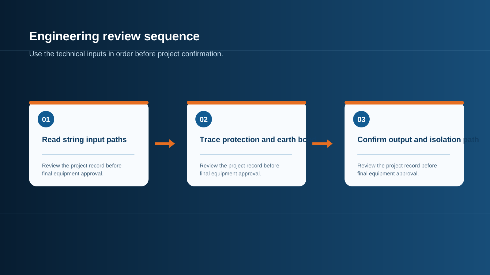
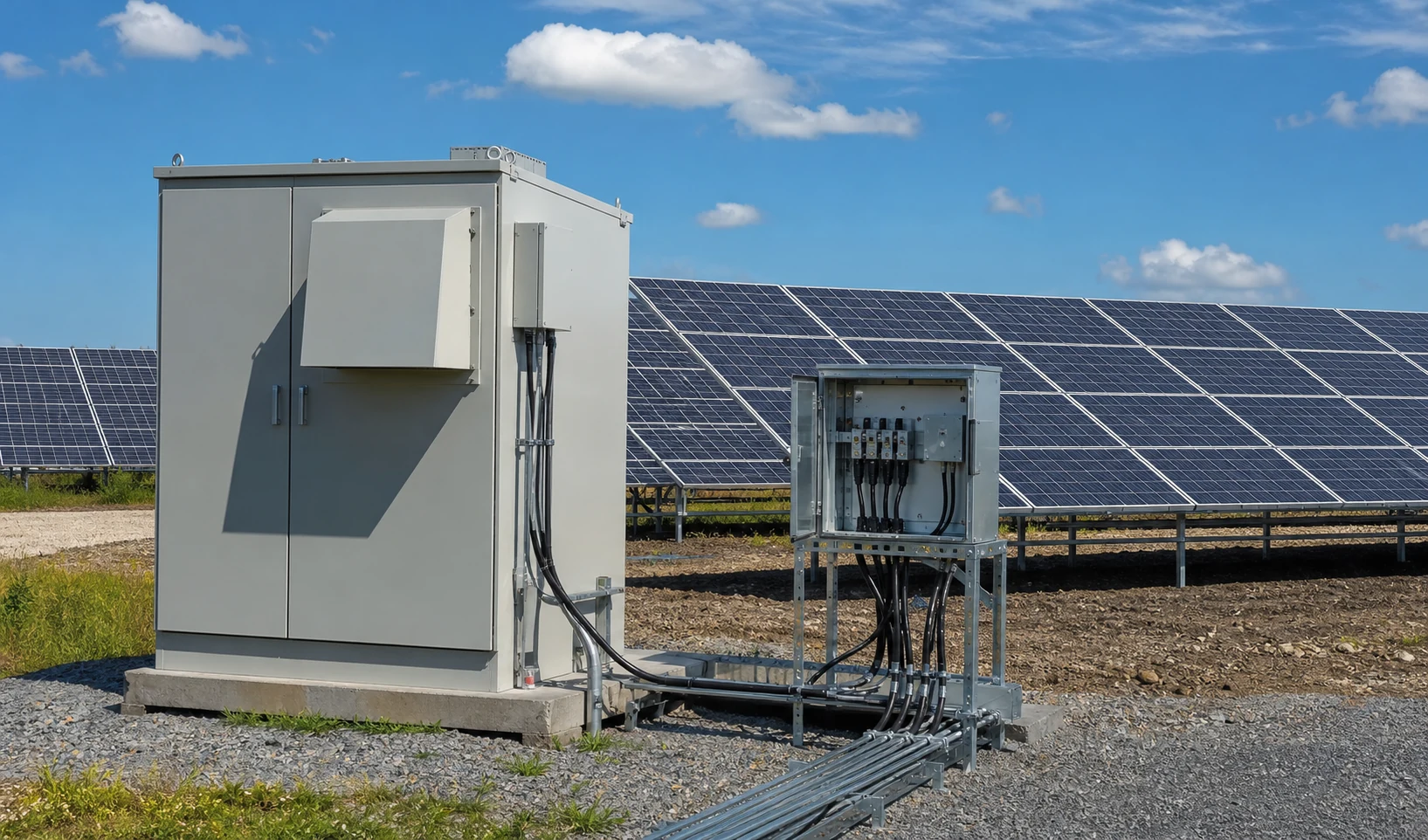
Technical diagram shown at a readable responsive scale.
SPD wiring
The surge protective device is wired across the DC bus, from the combined positive rail to the negative rail and to earth, depending on the coordinated protection scheme. Its earth lead runs to the PE bonding bar by the shortest practical route. On the diagram the SPD is drawn near the output side, with a distinct earth symbol.
- The SPD connects in parallel with the protected bus, not in series.
- Its earth path must be short and low-impedance to clip surges effectively.
- Status contacts, where fitted, report the SPD condition to monitoring.
Busbar and output
The protected string conductors land on the output busbar, which aggregates the current and feeds the DC disconnect switch. From the switch, a single positive and negative pair leaves the box toward the inverter or grid-connected cabinet. The busbar cross-section on the diagram must match the summed continuous current of all strings.
- Busbar rating = sum of all string currents, not a single string.
- The DC disconnect is the last device before the output terminals.
- Output conductors are sized for the total combined current with margin.
Grounding terminals
The PE bonding bar collects every earth connection: enclosure metalwork, door, gland plates, SPD earth and the array earth conductor. On the diagram it is the central earth symbol to which all protective conductors return. A continuous, low-resistance bond is what makes the protection scheme work during a fault or lightning event.
- All exposed conductive parts bond to the same PE bar.
- The array earth conductor enters and terminates on the PE bar.
- Continuity from every point back to the site electrode must be verified.
Terminal numbering and labels
Consistent numbering removes ambiguity on site. Inputs follow S1+/S1− ordering, the busbar is marked BUS+, BUS−, and the output is OUT+/OUT−. The diagram and the physical terminal markers must be identical so a technician can trace any conductor without guesswork.
- Use durable, legible labels that survive UV and temperature cycling.
- Keep the door schematic updated to the as-built configuration.
- Cross-check the diagram revision against the delivered unit.
Common diagram mistakes
Errors in the diagram propagate straight to the field. The most frequent issues are mismatched fuse ratings, an SPD drawn in series instead of parallel, missing earth bonds, and terminal numbers that do not match the enclosure. Catching these on the drawing review prevents rework and unsafe connections.
- Fuse rating below the 1.25×Isc requirement for the actual module.
- SPD shown in the live path rather than across the bus.
- Earth symbol present but no routed bonding conductor.
- Terminal numbers on the drawing differing from the installed markers.
This is general technical guidance. Confirm final ratings, protection coordination, installation and applicable local requirements against current standards, manufacturer documentation and the approved project design.
Frequently asked questions
What does a combiner box wiring diagram show?
It shows the full DC path: string inputs, per-string gPV fuses, the output busbar, the DC disconnect, the SPD across the bus, and the grounding and bonding connections, with terminal numbers for tracing.
Where does the SPD go in the wiring?
The SPD is wired across the protected DC bus — between the positive and negative rails and to earth — not in series with the live conductors. Its earth lead returns to the PE bonding bar.
How do I read terminal numbers?
Inputs are numbered S1+/S1− upward per string, the busbar is BUS+/BUS−, and the output is OUT+/OUT−. Match the drawing revision to the physical markers on the enclosure.
How do I check DC polarity on the diagram?
Follow each string pair from S n+ to the positive bus and S n− to the negative bus. The diagram should show consistent polarity so that all strings add, not cancel, at the output.
What are the most common wiring diagram mistakes?
Undersized fuses, an SPD drawn in series, missing earth bonds, and terminal numbers that differ from the installed enclosure are the usual errors that reach the field.
Discuss your PV combiner requirement
Share the system voltage, string count, inverter interface and installation environment. NEUTRON can review the equipment configuration around your project documentation.
Discuss a projectContinue learning
Explore related technical guidance in Solar PV.
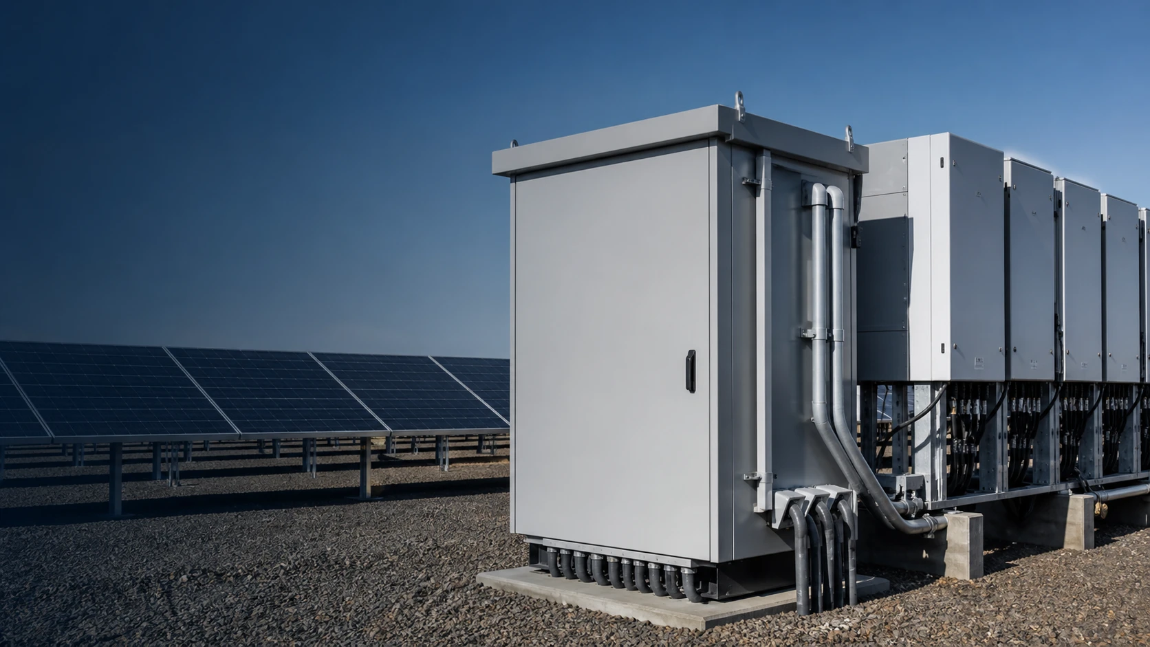

Published from the approved Period 09 source package. Technical values and final design decisions must be verified against the current applicable standard, manufacturer documentation and approved project design.