01
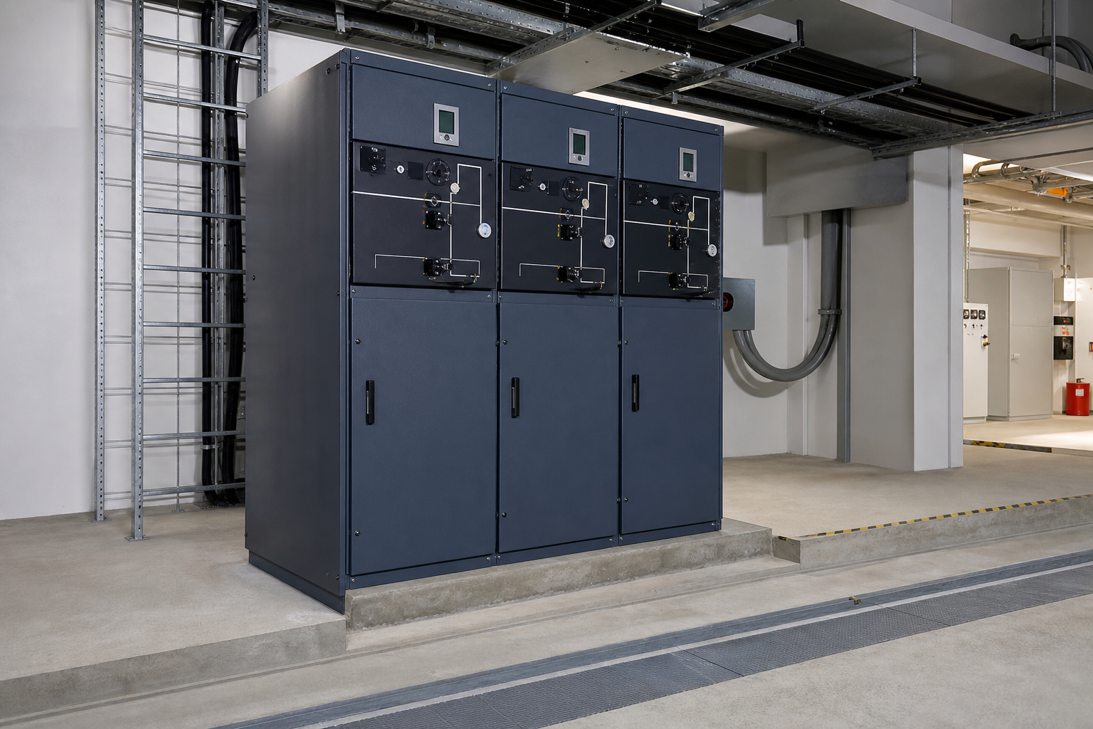
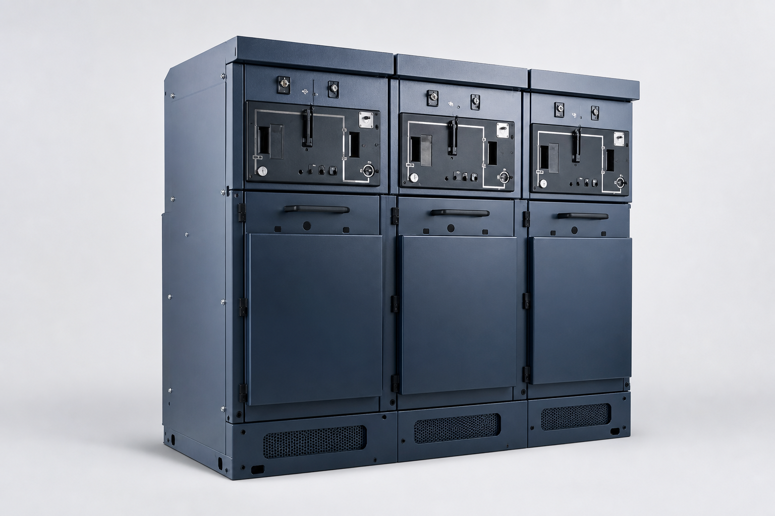
SF6 insulated RMU
Compact gas-insulated arrangement for project-defined MV switching
Confirm gas, pressure and maintenance requirements
 NEUTRONPower Distribution & New Energy
PV complete-set equipment
Keep the medium-voltage ring, protection, cable interfaces and remote-control path clear from the first project review.

Purchase readiness
Pricing is confirmed per configuration and quotation. Project builds are engineered to spec; final ratings, documents and delivery are confirmed before quotation.
Review point 01
Confirm circuit topology, cable interface, protection method and substation match as one reviewable scope.
Review point 02
Select the circuit count, operating arrangement, cable access and service clearance around the actual installation.
Review point 03
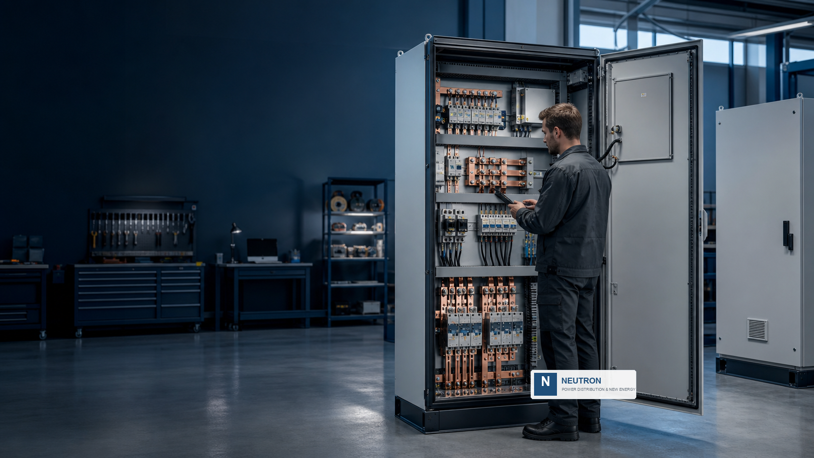
Define the DTU/FTU, I/O, protocol, local operation and SCADA responsibility before release.
Product range
Model, rating and component choices are confirmed from approved project inputs.
01
Compact gas-insulated arrangement for project-defined MV switching
Confirm gas, pressure and maintenance requirements
02
Alternative insulation approach for environmental and project requirements
Confirm applicable type and interface
03
Accessible MV arrangement for defined room and service conditions
Confirm footprint and clearances
04
Optional motorization, DTU/FTU and communications package
Confirm protocol and control points
Technical scope
| Typical voltage range | 12 / 24 / 40.5 kV starting points |
|---|---|
| Circuit arrangement | 2–6 circuits with LBS+Fuse, VCB, busbar, PT or metering modules as required |
| Protection and monitoring | Overcurrent, instantaneous, earth-fault and gas-pressure functions as specified |
| Insulation and enclosure | SF6, solid or air insulated; metal-enclosed arrangement with cable access |
| Operation | Manual or motorized operation with optional local/remote interface |
| Reference standards | IEC 62271-200 / IEC 62271-202 |
| Communication | Optional DTU/FTU, RS485, Ethernet and SCADA-ready interface |
Applications
Utility solar EPCs and developers
Compact ring nodes between step-up substations and the collection system
Switchgear and substation contractors
Defined transformer, cable and protection interfaces
C&I integrators and installers
Space-conscious medium-voltage connection and control
System position
The exact equipment boundary, interfaces and protection responsibility are confirmed against the approved single-line diagram.
Application profiles
The photographs show the operating context used in a technical discussion. Project-specific equipment, site evidence and final configuration are confirmed in the quotation package.
Application profile
Review voltage, footprint, cable entry, access and document requirements for this context.
Application profile
Review voltage, footprint, cable entry, access and document requirements for this context.
Application profile
Review voltage, footprint, cable entry, access and document requirements for this context.
Technical resources
Overview material for comparing the family and identifying the next technical question.
Request through project inquiry ->Technical packModel-level files matched to the confirmed configuration and revision.
Request through project inquiry ->Project setDefine the BOM, interface, inspection and handover documents for the workflow.
Request through project inquiry ->Related product families

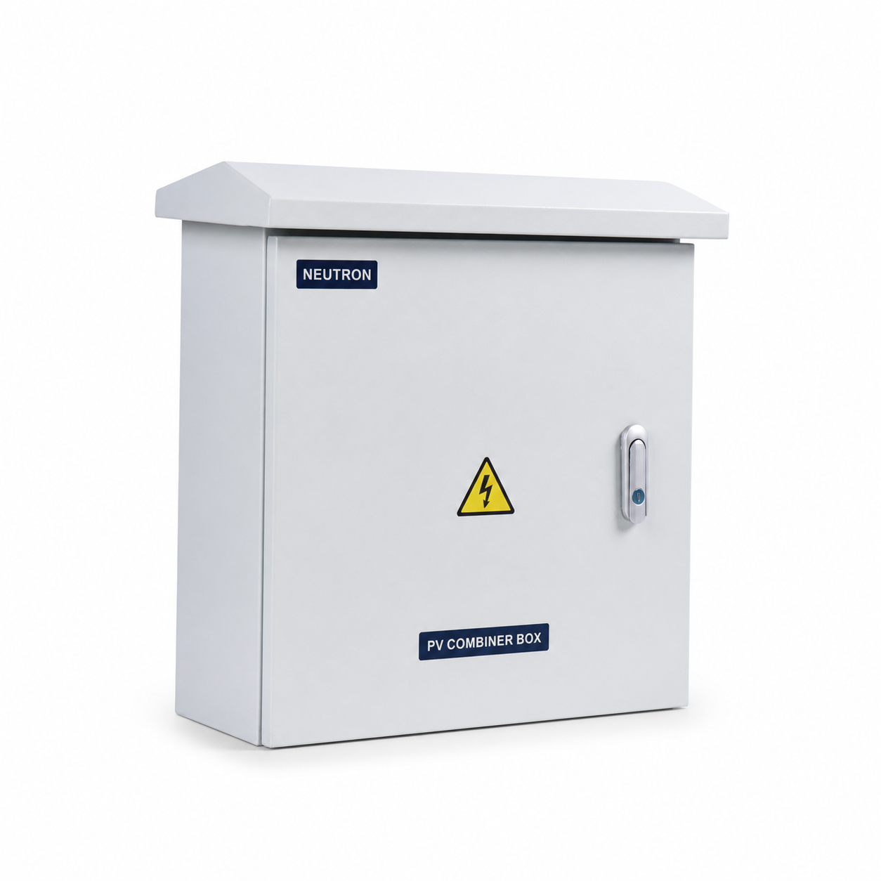
PV complete-set equipment
Move from inverter output to the medium-voltage collection system with a coordinated enclosure, interface and document review.
Solar PV distribution
Make every string, protection point and downstream interface easier to review before the quotation is released.
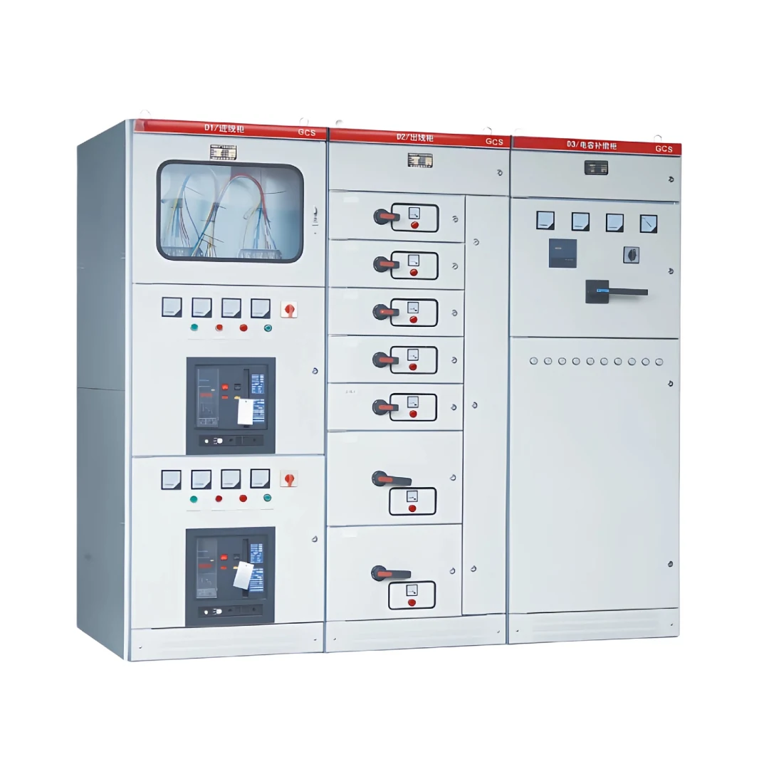
Low-voltage distribution
Move from a cabinet name to a buildable distribution arrangement with the right interfaces, access and documentation.
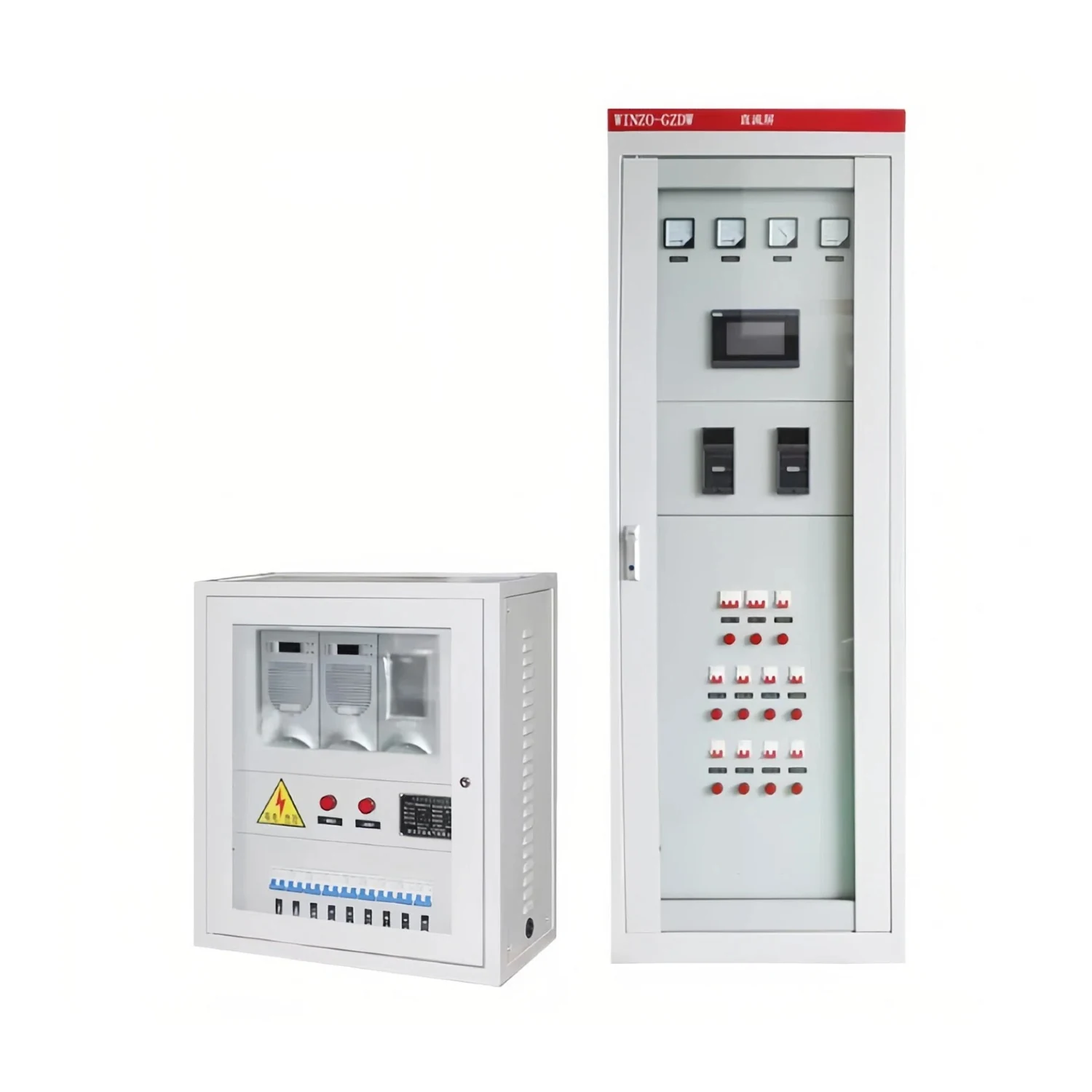
Protection and control
Keep control, protection, alarm and documentation interfaces visible from the first technical review.
FAQ
The planning range starts at 12, 24 and 40.5 kV. The final voltage, insulation method and switching arrangement are confirmed from the project design.
The starting range is 2 to 6 circuits. The approved ring topology, cable terminations, protection and metering requirements determine the final arrangement.
Optional motorization and DTU/FTU communication interfaces can be reviewed. Protocol, I/O, remote commands and control responsibility must be confirmed before release.
Compare the project environmental requirements, footprint, maintenance approach, applicable type, operating method and required documentation rather than selecting on voltage alone.
Yes. The product-family page is a starting point. Final enclosure arrangement, component selection, interfaces and documentation are confirmed against the approved drawing, load schedule or technical brief.
A single-line diagram, target ratings, quantity, installation environment, delivery destination and any required standards or document list will help the engineering review start with the right assumptions.
The review can include OEM, drawing-led assembly and project-specific integration requirements. Scope, interfaces, inspection points and document ownership are agreed before release.
No. This page explains the product family and the information needed for selection. The approved datasheet, drawing and quotation are the controlling documents for a specific project.
Next step
Application, destination, quantity, target ratings and document requirements make it easier to prepare a relevant response.