

Separate the physical link from the protocol
RS485 defines electrical signaling, while Modbus RTU defines serial messages and their interpretation. A common two-wire half-duplex network connects one polling client to several addressed devices. The installation also needs the reference, isolation and protection arrangements required by the chosen hardware.
Differential signaling improves noise tolerance only within receiver common-mode limits. It does not eliminate the need to evaluate potential differences, cable routing, transceiver loading or surge exposure. Maximum distance, node count and baud rate depend on the whole design, rather than one universal headline limit.
Build a linear bus with short stubs
Route the main twisted pair through successive nodes and keep branches short. A star of long cables can cause reflections and intermittent reception; use appropriate repeaters or separate segments when the site layout cannot support a suitable bus.
Identify the physical cable ends before enabling termination. Match end termination to the specified cable and transceiver design, commonly around 120 ohms, and avoid unnecessary termination at intermediate nodes. Check existing gateway switches and internal resistors so that the same end is not terminated twice.
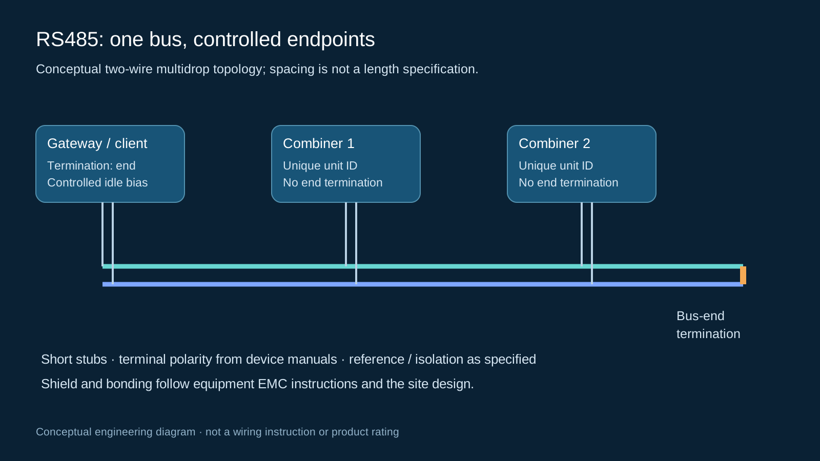
Technical diagram shown at a readable responsive scale.
Confirm polarity, bias and serial settings
A and B naming is not consistent across all vendors. Use the actual terminal definitions and signal polarity in both manuals rather than assuming letters correspond. Establish a controlled idle bias arrangement where required; several competing bias networks can load the line.
Every device on a segment must use compatible baud rate, parity and stop-bit settings. Do not treat 9600 baud or 8N1 as a universal default. Assign unique supported unit IDs; sequential numbers simplify documentation but are not a protocol requirement.
Map registers before trusting values
The device register map determines what can be read and how raw values become engineering quantities. Function 03 reads holding registers, function 04 reads input registers, function 01 reads coils and function 02 reads discrete inputs; use only functions implemented by the device.
Verify whether a manual uses a human-facing register number or a zero-based protocol offset. Confirm signedness, integer or floating-point format, scale, units, multi-register word order and invalid-value markers. CRC validation detects frame corruption, but it cannot correct a wrong register address or scaling factor.
| Layer | Confirm | Failure signature |
|---|---|---|
| Physical | Pair, reference, termination, bias | Timeouts or corrupt frames |
| Serial | Baud, parity, stop bits, unit ID | No reply or address conflicts |
| Application | Function, offset, type, scale, order | Plausible but incorrect values |
| Operational | Polling interval, freshness, quality | Old values shown as current |
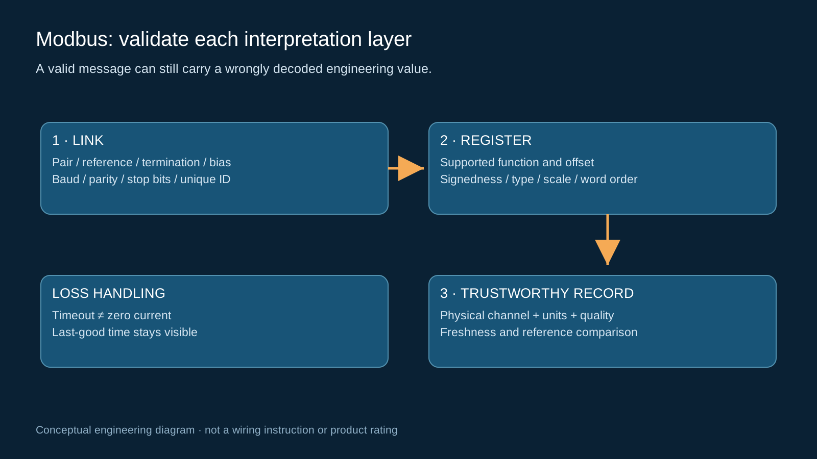
Technical diagram shown at a readable responsive scale.
Engineer shielding and reference paths
Keep communication wiring separated from power switching and surge-current routes, and use the cable, bonding and surge protection specified for the environment. Follow equipment EMC instructions and the site equipotential-bonding design.
Shield bonding is project-dependent. Single-end and multi-point strategies have different low-frequency and high-frequency behavior; a blanket rule to never bond both ends is inappropriate. The shield is not automatically the signal reference conductor. Where potential differences exceed the interface capability, evaluate galvanic isolation or another communication medium.
Set polling and timeout behavior
Budget request length, response length, processing time, serial timing and retry policy across the segment. Polling more quickly than devices can respond can increase retries without improving useful data. Retain last-good time and a separate quality state at the gateway.
A timeout means a value is unavailable, not that the measured string current is zero. Protect maintenance functions and write commands from accidental access. Traditional Modbus RTU is not an authenticated remote-control boundary.
Commission one device, then the full segment
Start with a known address and matching settings, verify a simple supported read, and compare a selected engineering value against an appropriate reference under controlled conditions. Expand to the full bus only after the basic channel is proven.
- Record addresses, serial settings, cable ends and termination positions.
- Verify measurement units, status bits and alarm states against the device documentation.
- Test device loss, gateway restart, recovery and stale-data handling.
- Check error counters during representative inverter and switching operation.
Troubleshoot from evidence
For no response, check power, address, settings and pair continuity before changing software. For intermittent faults, inspect topology, termination, common-mode conditions, shielding and surge damage. For stable but wrong numbers, inspect the register map and decoding first.
These are diagnostic starting points, not frequency statistics or proof of cause. Preserve configuration backups and the working commissioning record so later replacements use the same verified interpretation.
General engineering guidance, not a project design, product certificate or safe-work procedure. Verify ratings, isolation, protection coordination, software behavior and local requirements against the exact equipment documentation and approved project design.
Frequently asked questions
Is RS485 the same as Modbus?
No. RS485 is an electrical interface. Modbus RTU is a message protocol that can use that interface; compatible wiring alone does not establish a correct register map.
Must combiner addresses be sequential?
They must be unique and supported by the devices. Sequential addresses can help documentation but are not required for valid communication.
Where do termination resistors belong?
At the two physical ends of a suitable bus, matched to the cable and device design. Check existing termination and avoid adding it at every intermediate node.
Should the shield always be grounded at one end?
No universal rule applies. Follow the equipment EMC instructions and site bonding design, including potential differences, reference conductors and any required isolation.
Why can Modbus return plausible but wrong current?
A wrong offset, data type, scale or word order can produce a valid message with an incorrect engineering value. Compare the decoded result with the documented device map and a suitable reference.
Review your combiner monitoring requirement
Share the DC system voltage, string count, sensor and alarm requirements, existing gateway interface and installation environment so the proposed configuration can be reviewed against the project documentation.
Discuss a projectContinue learning
Explore related technical guidance in Solar PV.
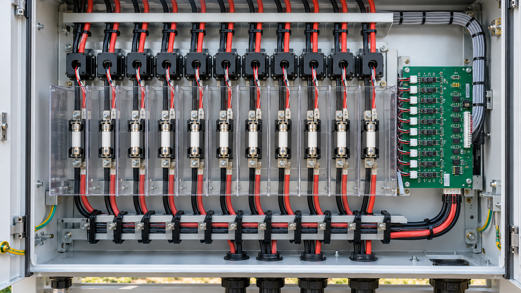


References describe general technology and documented scope. They do not certify a NEUTRON configuration or establish measured performance at a customer installation.