
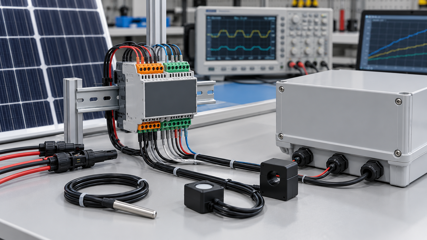
Define the module boundary
A data acquisition module receives current, voltage, temperature or status inputs and converts them into engineering values for a local controller or plant network. It may also filter signals and generate monitoring alarms. The exact functions depend on the selected hardware and firmware.
Start with a channel schedule and interface specification. List each input type, source, range, required accuracy, update interval and physical identifier. A smart combiner needs a verified data path, not simply a module described as its brain.
Match input range and insulation to the circuit
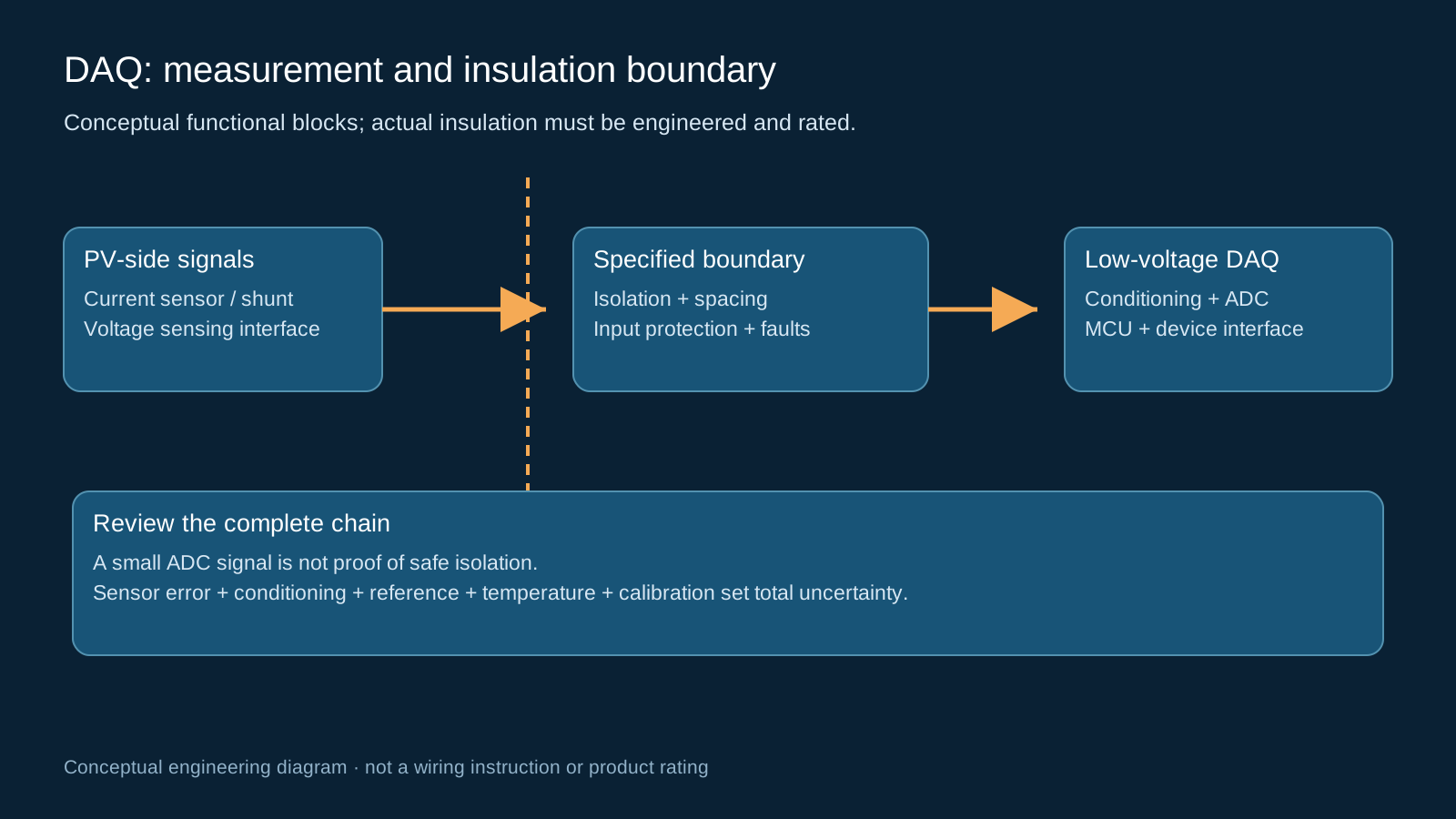
String current can be measured with suitable Hall transducers or shunt-based circuits. A shunt itself does not provide isolation. Bus voltage measurement needs an appropriately engineered sensor or divider and isolation arrangement; scaling voltage into an ADC range does not by itself protect the low-voltage electronics.
Review working voltage, transient stress, creepage, clearance, input protection and fault behavior across the complete assembly. Check the exact channel interface against the sensor output type. The specification must account for both normal operation and credible faults, including a disconnected input.
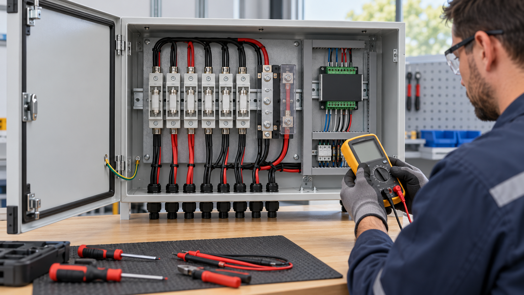
Technical diagram shown at a readable responsive scale.
Separate resolution from measurement accuracy
ADC bit depth describes digital resolution. Total channel error also includes sensor accuracy, offset, reference error, conditioning, noise, temperature drift and calibration uncertainty. State whether a quoted limit applies to reading, full scale or a defined operating range.
Calibrate the relevant channels against a suitable reference at specified points and conditions. Retain coefficients and version information through maintenance or firmware updates. Temperature compensation is only effective within its validated model and range; it does not make every channel seasonally invariant.
Make preprocessing and derived values explicit
Filtering and averaging can improve stability but add latency. Define the sample interval, filter window and published update rate so an operator knows what an alarm or trend represents. Closely align current and voltage samples when calculating estimated DC power.
A sum of current channels is a calculated total, not an independent measurement of output current. DC power derived from sampled voltage and current is an estimate with a defined uncertainty; it is not equivalent to calibrated plant energy metering or a complete performance-ratio calculation.
Document registers and data validity
For Modbus RTU, provide the supported function codes, addresses or offsets, channel order, signedness, scale, units and multi-register word order. Keep alarm and quality bits distinct from measured values and identify any writable parameters.
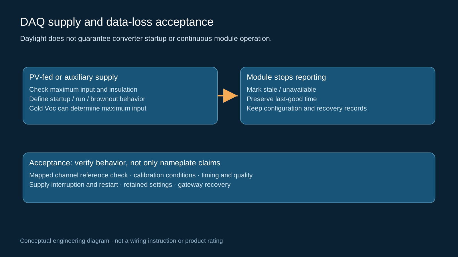
A gateway must preserve a last-good timestamp and flag stale data when communication fails. A frozen value, invalid marker or restarted module must not silently become zero current. If acquisition time is unavailable, label the gateway polling time accurately.
Choose a supply with a known operating envelope
Modules may use an auxiliary low-voltage supply or a suitably rated converter fed from the PV circuit. Neither architecture is universal. For a PV-fed converter, check maximum cold open-circuit voltage, minimum start and run voltage, insulation and surge requirements against the actual design.
An illuminated array does not guarantee that a converter starts or stays above its operating threshold. Define night behavior, brownout recovery, configuration retention and reporting after supply loss. An isolated DC-DC converter is only one boundary and does not validate isolation on every input or communication port.
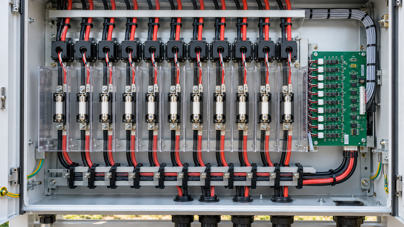
Technical diagram shown at a readable responsive scale.
Integrate without degrading the assembly
Plan sensor wiring, cooling space, service access and separation between measurement, communication and power circuits. Check channel loading, terminals, cable glands, enclosure sealing and EMC behavior after integration. Confirm environmental limits for the assembled enclosure rather than only the module datasheet.
Monitoring electronics supplement the protection arrangement. They do not replace coordinated fuses, disconnectors, surge protection or required protective functions. Preserve the approved safe-work and isolation procedures during testing and maintenance.
Use a procurement and acceptance checklist
Request documentation that allows the exact delivered variant to be commissioned and maintained.
| Item | Evidence to request |
|---|---|
| Measurement | Channel ranges, total error limits, calibration conditions and update rate |
| Electrical boundary | Working-voltage and insulation specifications for each relevant interface |
| Supply | Start/run limits, maximum input, brownout and night behavior |
| Communication | Register map, firmware version, quality flags and write controls |
| Acceptance | Mapped channel tests, reference comparison, loss/recovery and retained settings |
General engineering guidance, not a project design, product certificate or safe-work procedure. Verify ratings, isolation, protection coordination, software behavior and local requirements against the exact equipment documentation and approved project design.
Frequently asked questions
What does a combiner DAQ module do?
It converts supported sensor and status inputs into digital values, applies defined preprocessing and exposes measurements and diagnostics to a plant interface.
Does a high-resolution ADC guarantee accurate measurements?
No. Accuracy depends on the complete sensor, conditioning, reference, conversion and calibration chain, including temperature effects and operating range.
Is a voltage divider enough to connect a PV bus to a controller?
No. The complete measurement design must address working voltage, isolation, spacing, transient protection and fault behavior. A scaled signal alone is not a safe interface design.
Will a PV-fed module operate whenever there is light?
Not necessarily. Its converter needs the specified startup and operating conditions. Define night operation, brownout and supply-loss reporting explicitly.
What should happen when the DAQ stops responding?
The gateway should mark data as unavailable or stale, preserve last-good time and generate the appropriate diagnostic. It must not treat the communication failure as measured zero current.
Review your combiner monitoring requirement
Share the DC system voltage, string count, sensor and alarm requirements, existing gateway interface and installation environment so the proposed configuration can be reviewed against the project documentation.
Discuss a projectContinue learning
Explore related technical guidance in Solar PV.
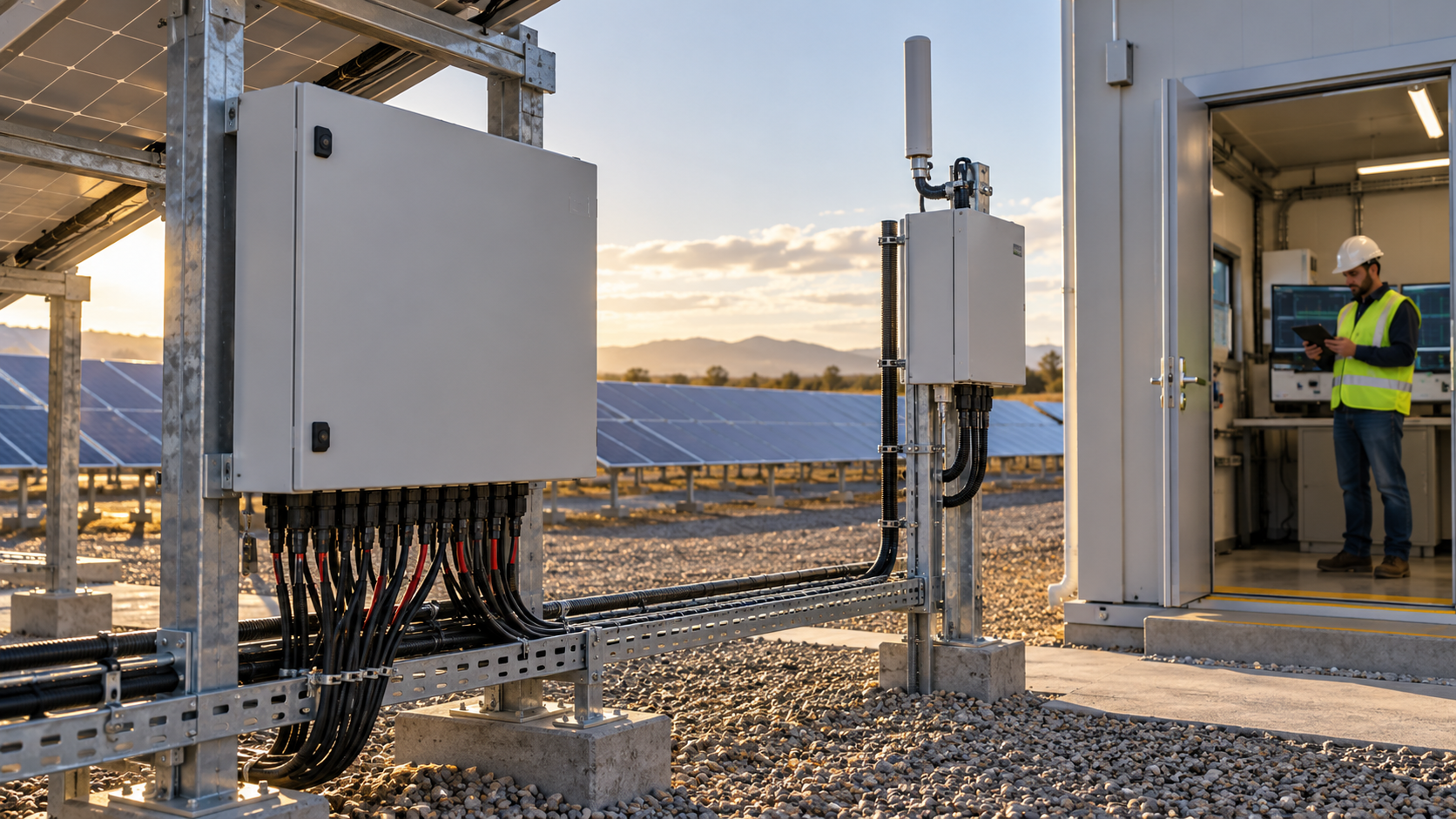
References describe general technology and documented scope. They do not certify a NEUTRON configuration or establish measured performance at a customer installation.