
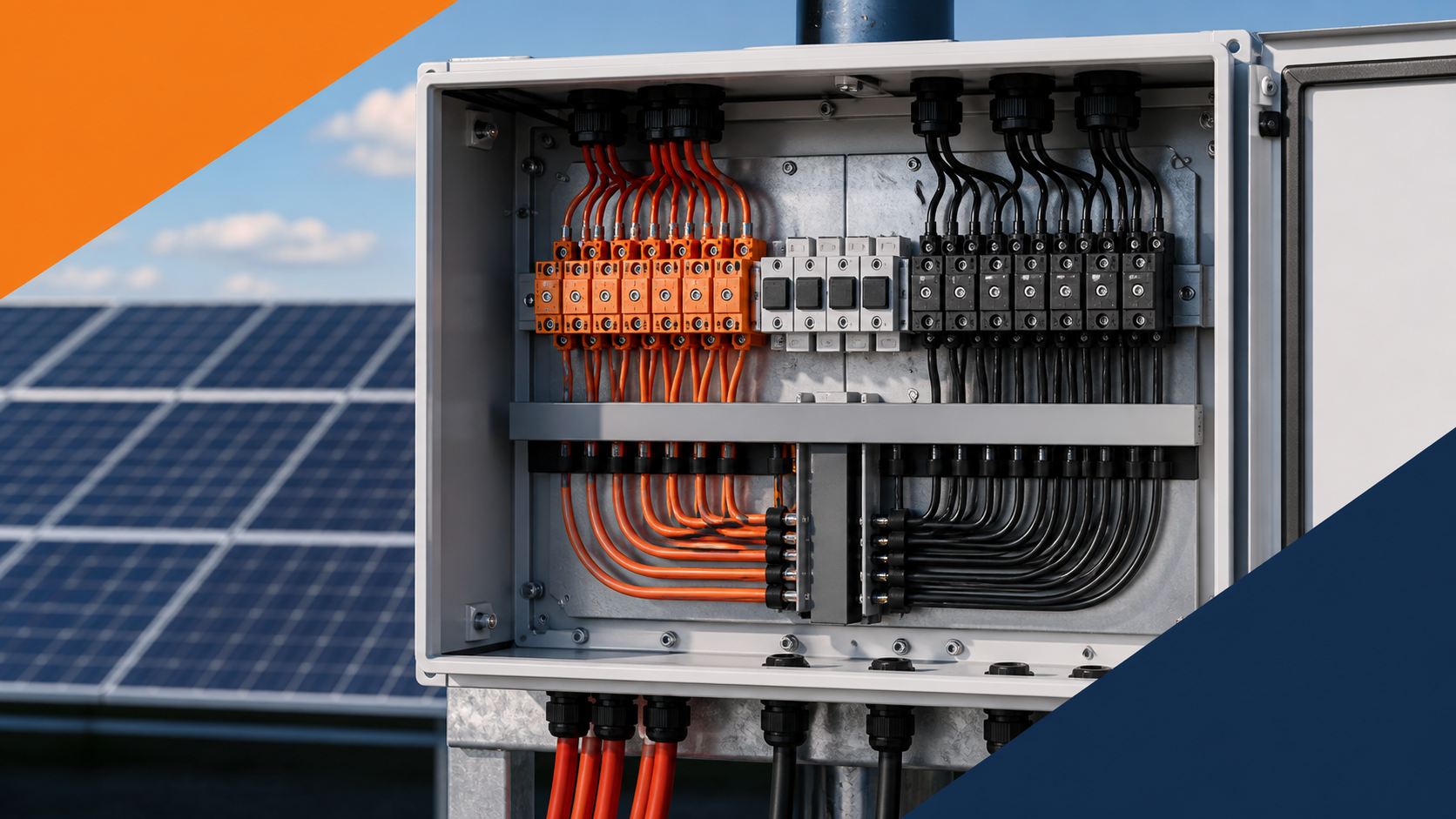
What reverse polarity does
A PV module is a current generator with a fixed polarity. When a string is reversed at the combiner input, its current opposes the others, reducing the total output and creating a local imbalance on the busbar. In a fused design the reversed string may also see reverse stress through the protection path, so the fault is not always obvious until measured.
- Output current drops because the reversed string subtracts.
- The busbar sees an unbalanced load that can overheat.
- The fault may pass a visual check yet fail a polarity test.
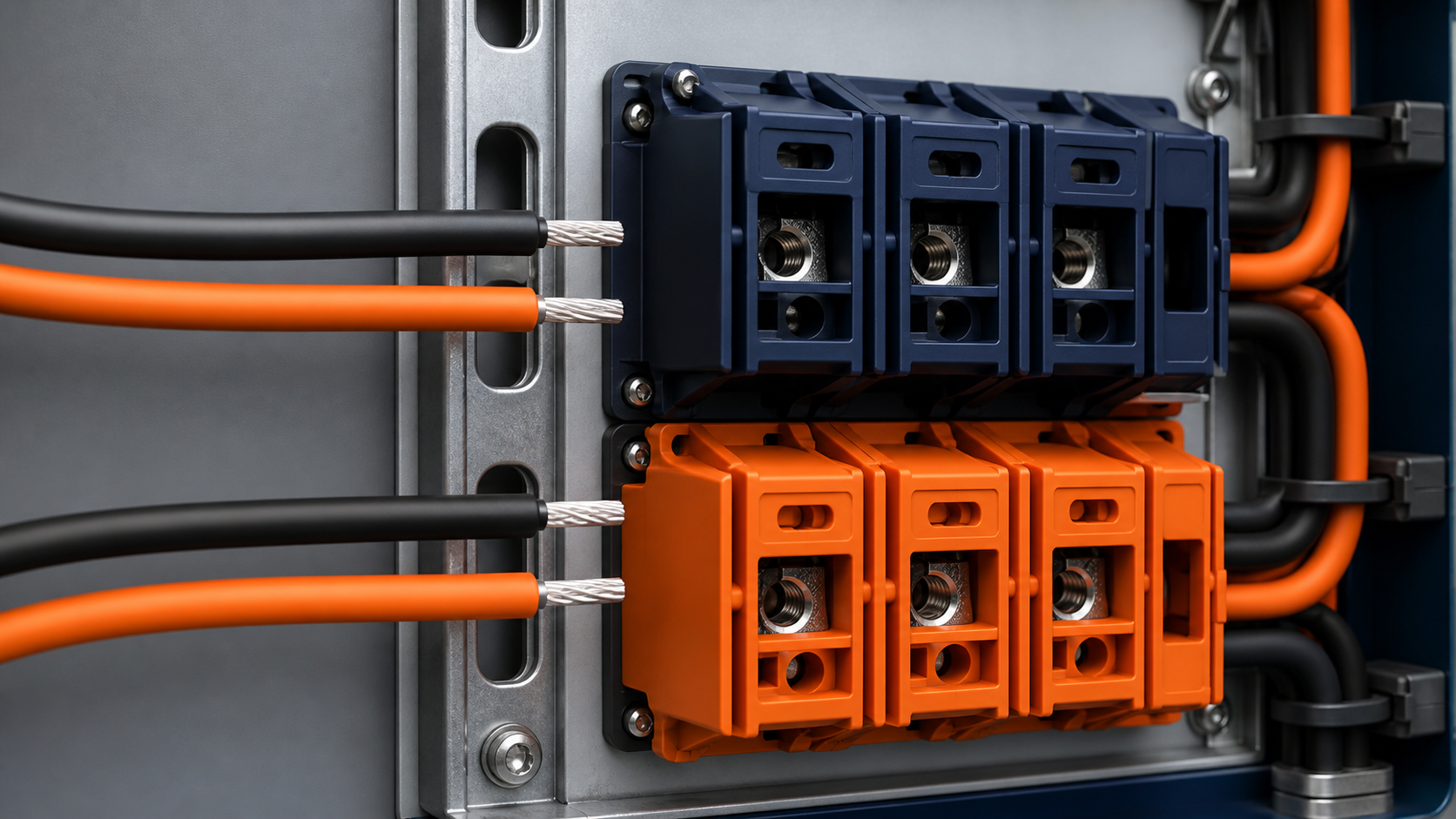
Colour coding and labels
Consistent colour coding is the first defence. The positive conductor is marked red and the negative black, and every gland, terminal and label carries the same convention. A string schedule at the door removes any doubt about which pair belongs to which input.
- Use red for positive and black for negative throughout the DC run.
- Label each string pair at both the array end and the box.
- Keep a door schedule that maps S n+ and S n− to physical terminals.
Pre-connection multimeter test
Before landing a conductor, verify polarity with a multimeter at the cable end. A quick voltage reading confirms which conductor is positive so it is never offered to the wrong terminal. This check takes seconds and prevents a reversed termination that is awkward to undo later.
- Measure open-circuit voltage and note which lead is positive.
- Match the positive lead to the + terminal on the schedule.
- Repeat per string; do not assume adjacent strings share orientation.
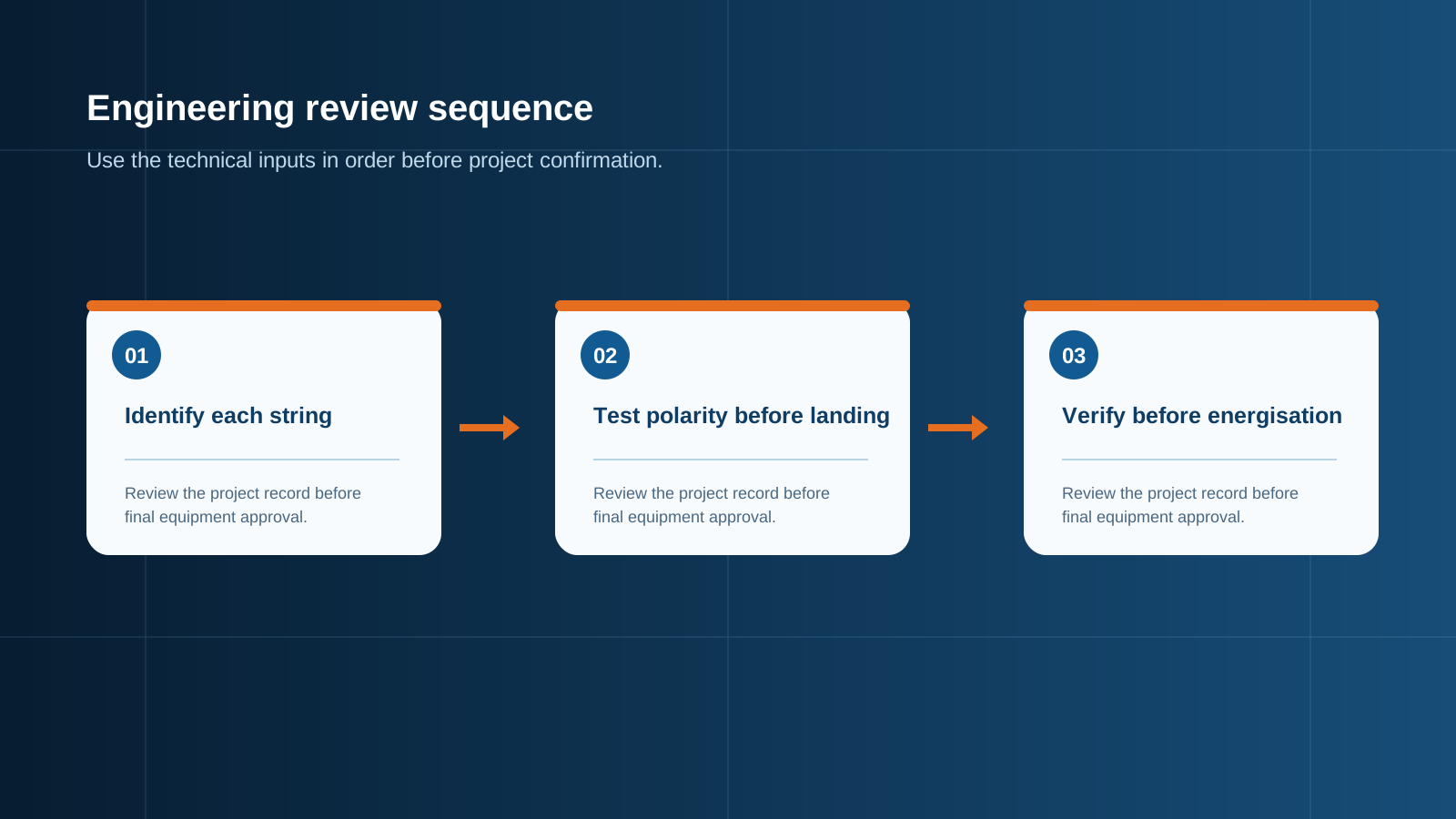
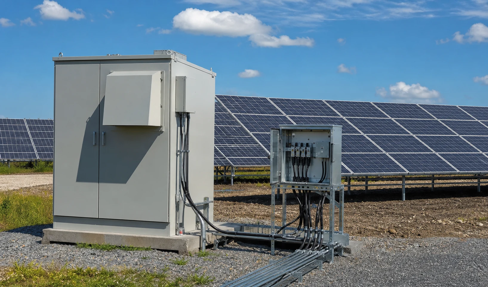
Technical diagram shown at a readable responsive scale.
Anti-reverse terminal design
NEUTRON combiner boxes use keyed or shrouded terminal arrangements that make a wrong insertion physically difficult. Polarised connectors and clearly separated + / − blocks reduce the chance of a field error, and a good layout keeps each string pair visually distinct.
- Use polarised connectors that cannot mate the wrong way.
- Separate the + and − blocks so crossing is obvious.
- Provide a marked, shrouded terminal only for the correct polarity.
Blocking diode role
A blocking diode can be placed so that a reversed string cannot feed current backward through the shared busbar. While modern fused combiner designs rarely rely on diodes alone, the principle remains: the protection path should let correct-polarity current through and block the reverse direction. Any such device must be rated for the string current and the system voltage.
- A blocking diode passes forward current and blocks reverse current.
- It must be rated for the string Isc and the system voltage.
- It is a supplementary measure, not a substitute for correct wiring.
Commissioning verification
Commissioning includes a polarity verification at every input before the DC isolator is closed. The multimeter check at the box confirms S n+ is positive relative to S n− and that the output polarity matches the inverter requirement. Only after this passes is the array energised.
- Verify each input polarity with the isolator OFF.
- Confirm output polarity matches the downstream equipment.
- Record the check as part of the commissioning log.
Field failures
The usual field failures are a mis-labelled string at the array, a crossed pair in a long conduit run, or a connector assembled the wrong way. Each shows up as reduced output or a hot terminal and is found only by testing. Good labelling and a pre-connection test stop most of them before they are energised.
- Mis-marked positive and negative at the module junction.
- A crossed pair where two conduits meet.
- A connector crimped with reversed inserts.
Prevention checklist
A short checklist keeps polarity correct from the array to the box. It combines marking, testing and design features so that a single oversight is caught by the next step rather than reaching the live bus.
- Mark and label every conductor red/black at both ends.
- Multimeter-test polarity before landing each string.
- Use polarised, keyed terminals at the combiner box.
- Verify all inputs during commissioning before closing the isolator.
This is general technical guidance. Confirm final ratings, protection coordination, installation and applicable local requirements against current standards, manufacturer documentation and the approved project design.
Frequently asked questions
What does reverse polarity cause in a combiner box?
A reversed string subtracts from the array output instead of adding, unbalancing the busbar and hiding a fault that can later appear as a hot or degraded connection. It is not always visible on a visual check.
How do I test for reverse polarity?
With a multimeter at the cable end or at the box input, confirm the positive lead is red and measures positive relative to the negative. Match each lead to its marked terminal before landing it.
What role does a blocking diode play?
A blocking diode passes forward current and blocks reverse current, so a reversed string cannot feed backward through the shared busbar. It must be rated for the string current and system voltage and is a supplementary measure rather than a replacement for correct wiring.
Which colour code should I use?
Use red for the positive conductor and black for the negative throughout the DC run, and label each string pair at both ends plus on the door schedule so there is no ambiguity at the combiner box.
How can reverse polarity be prevented?
Combine consistent red/black marking, a multimeter polarity test before landing each string, polarised keyed terminals at the box, and a commissioning polarity verification before the DC isolator is closed.
Discuss your PV combiner requirement
Share the system voltage, string count, inverter interface and installation environment. NEUTRON can review the equipment configuration around your project documentation.
Discuss a projectContinue learning
Explore related technical guidance in Solar PV.

Published from the approved Period 09 source package. Technical values and final design decisions must be verified against the current applicable standard, manufacturer documentation and approved project design.