

Map the array and service boundary
Building integrated photovoltaics (BIPV) use PV modules as part of a roof, facade or glazing system. The electrical collection design therefore has to fit a building envelope that may become difficult to access after installation. Start with the module layout, string grouping, inverter inputs and ownership of each isolation and maintenance task.
Mark the proposed combiner location on the coordinated building drawings. Record which circuits enter and leave the enclosure, where conductors pass through fire or weather barriers, and how a technician will identify and isolate the correct circuit. The current consolidated IEC 62548-1 covers PV array design topics including DC wiring, electrical protection, switching and earthing; it does not replace building codes or the project design.
- Show location and service clearance on the drawing set.
- Identify circuit labels and the responsible maintenance team.
- Coordinate penetrations with facade, roofing and fire-separation details.
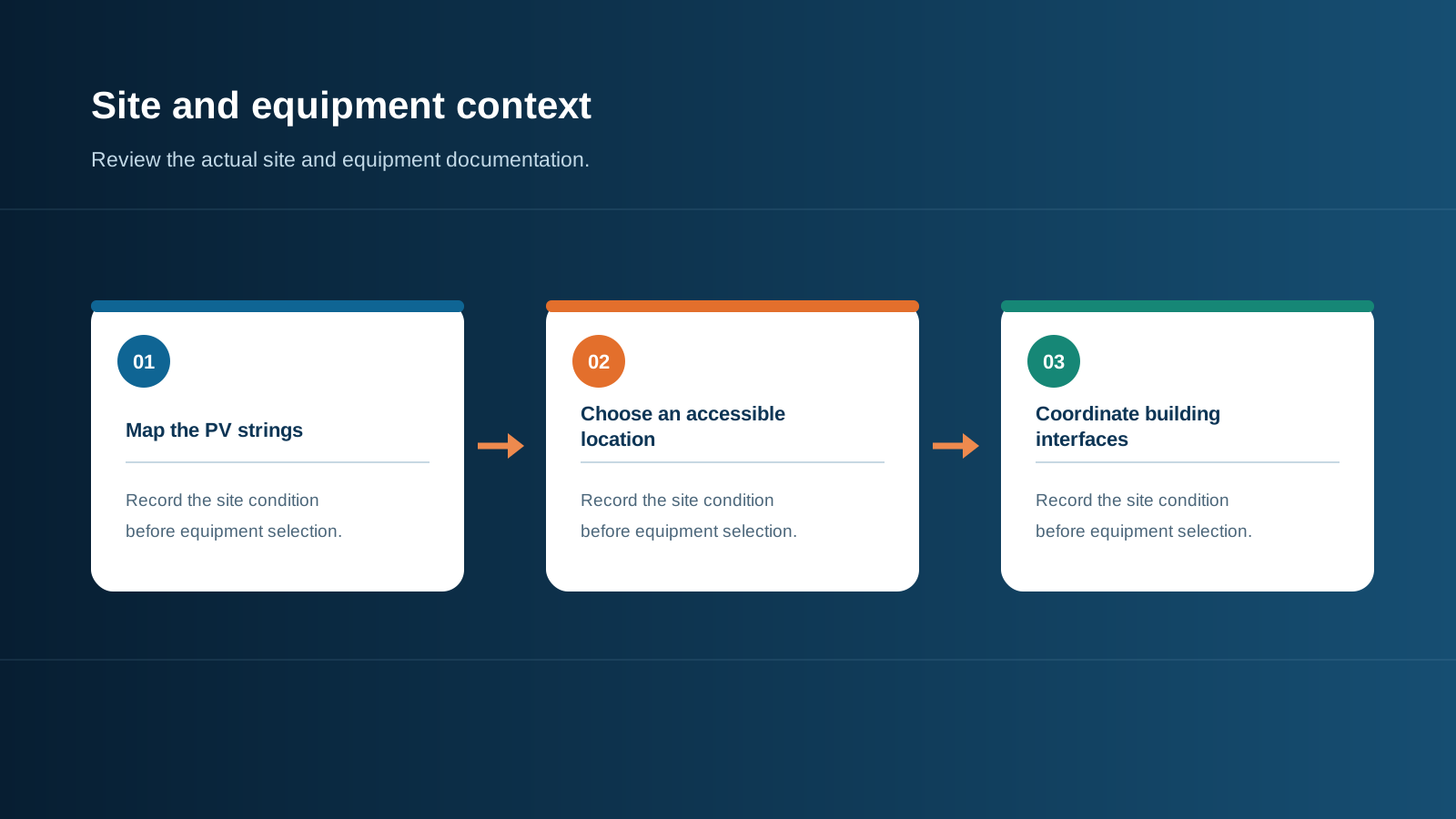
Technical diagram shown at a readable responsive scale.
Place equipment for access before closeout
A visually discreet location still needs a safe, practical service path. Do not place a box where access requires removing sealed cladding, working above a public route, reaching across other services or opening a restricted space without an agreed method. Confirm the mounting surface and support loads with the relevant design team.
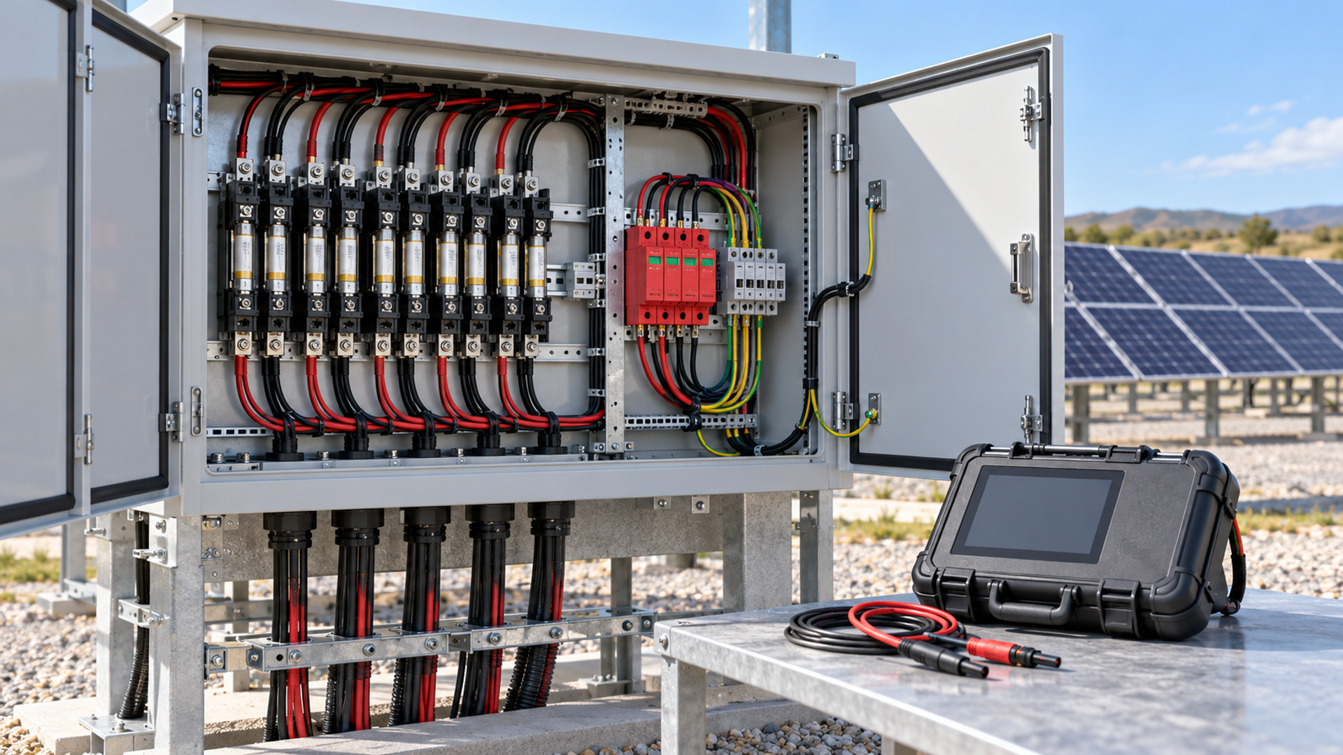
Check enclosure depth, door swing, conductor bend space, working clearance and room for test equipment against the actual construction drawings. A smaller box is not automatically a better BIPV choice if it makes termination, inspection or component replacement impractical.
- Confirm the door opens fully after adjacent finishes are installed.
- Keep service access clear of glazing hardware and unrelated equipment.
- Document any access panel or removable cladding maintenance depends on.
Match enclosure protection to its location
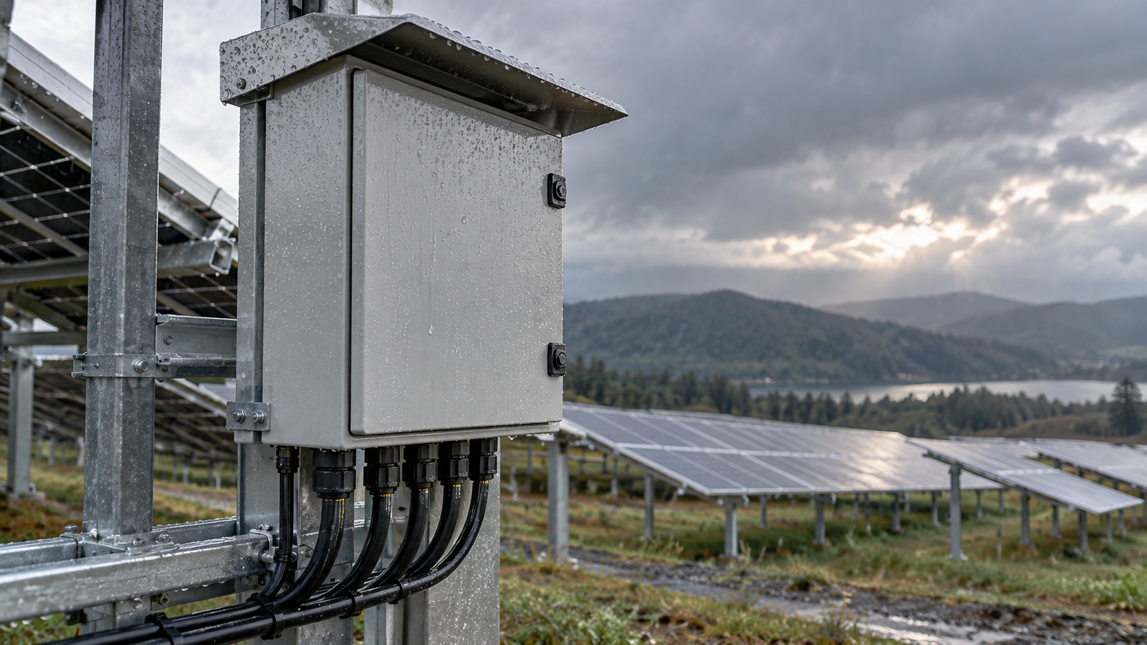
An enclosure inside a dry electrical room faces different water, dust, sunlight and temperature exposure than one behind a facade or at a roof edge. Select the required ingress protection from the site conditions and installation details. IEC 60529 defines an IP classification system; the marked rating applies to a tested configuration and should not be treated as proof that every cable entry or field modification retains the same protection.
List the exposure at the mounting plane: wind-driven rain, condensation, cleaning water, dust, solar heating and expected temperature range. Check the enclosure, glands, blanking plugs, door seal and installation method as a complete assembly against manufacturer instructions.
- Avoid assigning one IP value to every BIPV project.
- Confirm penetrations and accessories are within the documented rating.
- Check thermal performance in the chosen mounting cavity.
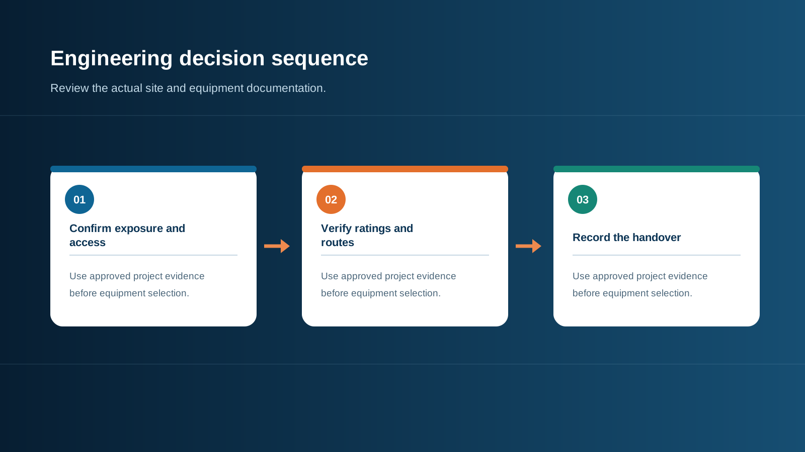
Technical diagram shown at a readable responsive scale.
Coordinate fire requirements and DC wiring
Cable type, route, segregation, fire stopping and access requirements depend on the building use and jurisdiction. Obtain the applicable fire strategy and electrical rules from the project team; a combiner box alone cannot make a BIPV installation code-compliant. IEC 61439-2:2020 covers power switchgear and controlgear assemblies, including PV-related provisions, but the applicable conformity route must be chosen for the actual equipment and jurisdiction.
Keep PV conductors identifiable and route penetrations so the intended building barriers are maintained. Record how the installation will be isolated, tested and handed over, including conductors that remain energized under daylight conditions.
- Do not state a cable fire class without the project specification.
- Show fire-stopping responsibility and inspection points.
- Preserve access to required labels and isolation devices.
Coordinate voltage, protection and monitoring
Calculate array maximum DC voltage from module data, series count and the approved design-temperature method. Match fuses, switching equipment, insulation and surge protection to those values and fault-current conditions. IEC 61643-31 addresses PV DC surge protective device requirements and testing; it does not select the complete building lightning-protection design.
If monitoring is required, identify whether the building management system receives a dry-contact state, per-string measurement or gateway data. List signal ratings, isolation, data mapping, alarm meaning and communication-failure behavior. An alarm needs a defined response and cannot replace electrical protection.
- Define monitored points and the recipient system before procurement.
- Confirm exact device ratings and interface from current manufacturer documents.
- Keep monitoring and switching functions distinct in the drawings.
Technical diagram shown at a readable responsive scale.
Use a BIPV release checklist
Before ordering, close the drawing review across the PV engineer, architect, electrical contractor and building-safety team. Confirm the exact mounting location, weather exposure, access path, DC circuit schedule, maximum system voltage, required protection and interface to the inverter and building systems.
Retain the approved drawings, product schedules, installation instructions and commissioning record together. The owner should be able to locate the equipment, identify its circuits and understand the maintenance boundary after facade work is complete.
- Approve location, mounting and service access.
- Document enclosure rating and all entries.
- Record circuit ratings, interface, labels and handover duties.
General engineering information, not a project design, product certificate, code determination or safe-work procedure. Verify final ratings, installation, protection coordination and local requirements against current standards, exact manufacturer documentation and the approved project design.
Frequently asked questions
Does every BIPV combiner box need a compact enclosure?
No universal size follows from the BIPV label. Select dimensions from circuit count, component clearances, conductor space, thermal conditions, service access and the approved building layout.
What IP rating should a BIPV combiner box use?
Use the actual mounting exposure and installation details to set the requirement. Verify the marked IP classification and every field entry against enclosure documentation; indoor and weather-exposed locations do not share one automatic rating.
Can the combiner box make a building PV system fire-code compliant?
No. Cable selection, routing, penetrations, separation and isolation must follow the approved project design and local building and electrical rules. The box alone cannot establish compliance.
What should be coordinated before a facade is closed?
Confirm equipment location, access, door clearance, conductor routes, penetrations, circuit labels, isolation and the maintenance method on the coordinated drawings.
Does IEC 61439-2 cover the complete BIPV installation?
It addresses power switchgear and controlgear assemblies, including PV-related provisions. It does not by itself approve the building envelope, local code compliance or the full project installation.
Review the project inputs
Share the system voltage, circuit schedule, installation location and site conditions so the equipment discussion can be checked against approved project documentation.
Discuss a projectContinue learning
Explore related technical guidance in Solar PV.
Prepared from the approved Period 09 source package with technical claims revised to retain project-specific and manufacturer-specific limits. Official source pages describe scope; they do not certify a NEUTRON product configuration or a customer installation.