
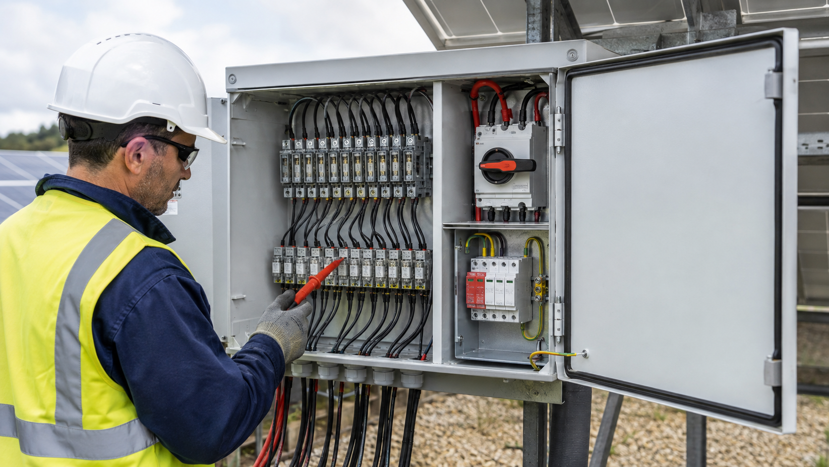
Breaker frequent tripping
A DC circuit breaker that trips repeatedly is the most reported combiner box fault. The trip is a symptom, not the disease: it shows the protective device is doing its job against an overcurrent, a ground fault or a sustained overload. Start by isolating which input string feeds the breaker, then measure that string for short circuit, reverse polarity or insulation breakdown before resetting.
- Record the trip current and whether it occurs at dawn, midday or under cloudy fluctuation.
- Compare the string Isc against the breaker rating — a mismatch points to a sizing error, not a fault.
- Never upsize the breaker to stop nuisance trips; that removes protection and risks a fire path.
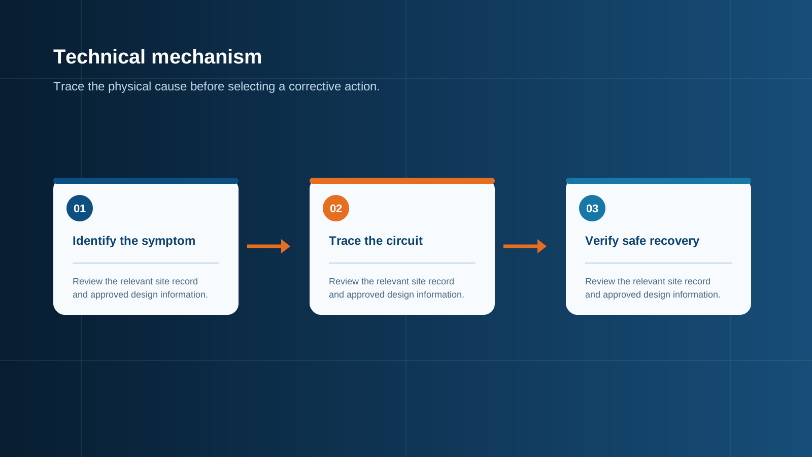
Technical diagram shown at a readable responsive scale.
SPD failure
Surge protective devices absorb lightning and switching transients. An SPD fails either by safely disconnecting (end-of-life) or by thermal runaway if its internal varistor degrades. Modern Type 1+2 DC SPDs include a visual status window and a remote signalling contact, so a failed module is usually visible without opening the enclosure. A degraded SPD left in circuit can overheat the whole busbar.
- Check the green/red indicator at every site visit.
- Confirm the remote alarm reaches the monitoring platform.
- Replace on confirmed failure using the same Uc and Up envelope.
Internal over-temperature
Heat inside the box comes from I2R losses in busbars and terminals, plus solar gain on a dark enclosure. When internal temperature exceeds the rating of the fuse or SPD, protection performance drops and the breaker may trip on thermal basis. A combiner box that runs hot in summer needs either better ventilation, a larger cross-section busbar or a lower continuous load.
- Fit a temperature sensor on the busbar near the output terminal.
- Set an alarm threshold below the lowest component rating.
- Re-evaluate enclosure colour and solar exposure for roof-mounted units.
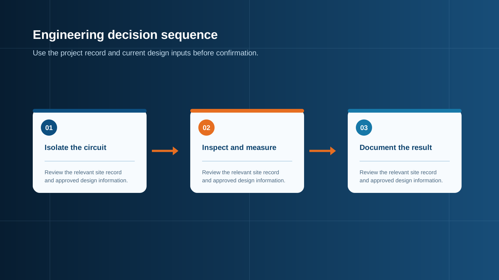
Technical diagram shown at a readable responsive scale.
Terminal overheating
Loose or under-torqued terminals are a leading cause of hot-spot fires in DC assemblies. As contact resistance climbs, the terminal dissipates more heat, which further loosens the joint — a runaway loop. Infrared inspection during a loaded condition is the reliable way to catch a heating terminal before it discolours the enclosure.
- Re-torque all power terminals on a fixed schedule.
- Use anti-oxidation paste on aluminium conductors where specified.
- Replace any terminal block that shows annealing or melting.
Comms / monitoring loss
Many combiner boxes report string current, breaker state and SPD status to a SCADA or cloud platform. A lost comms link hides every other fault, so it must be treated as a priority. The cause is usually power to the logger, a damaged RS485/CAN cable, or a configuration mismatch after a controller swap — not the protection devices themselves.
- Verify 24 V or 12 V auxiliary supply at the logger.
- Check the bus cable shield and termination at both ends.
- Confirm the station ID and baud rate after any hardware change.
Fuse blown
A gPV fuse blows to clear a string fault or an overcurrent the breaker did not catch in time. A single blown fuse drops one string's output and is easy to miss on a large array. The correct response is to find why it blew — a shorted module, reverse polarity, or an undersized fuse against real bifacial Isc — before fitting a replacement.
- Never bridge a blown fuse with a conductor; that removes string protection.
- Match the replacement to IEC 60269-6 gPV and the 1.25x Isc rule.
- Log the string position; repeated blows on one input point to a recurring defect.
Diagnostic tools
A consistent toolbox turns guesswork into a measured diagnosis. The essentials are a true-RMS DC clamp meter, an insulation tester (500 V/1000 V), a thermal camera and the monitoring portal. Used together they isolate a fault to a single string in minutes rather than hours of panel-by-panel checking.
- DC clamp meter — measure per-string current and balance.
- Insulation resistance tester — find ground faults safely from the disconnect.
- Thermal camera — reveal terminal and busbar hot spots under load.
- Monitoring portal — confirm comms, alarm history and trend data.
Maintenance plan
Most combiner box faults are preventable with a scheduled routine. A six-month visual and torque check, a yearly thermal scan and an SPD status review keep the box inside its design envelope and give early warning before a fault becomes an outage. NEUTRON documents a maintenance discussion around each project so the plan matches the site class.
- Quarterly: SPD status, comms check, alarm review.
- Bi-annual: torque re-tighten, seal and gland inspection.
- Annual: full thermal imaging and internal clean.
This is general technical guidance. Confirm final ratings, protection coordination, installation and applicable local requirements against current standards, manufacturer documentation and the approved project design.
Frequently asked questions
What are the most common PV combiner box faults?
The recurring faults are breaker tripping, SPD failure, internal over-temperature, terminal overheating, communications loss and blown gPV fuses. Most trace back to sizing errors, loose terminals or missing maintenance rather than component defects.
Why does a combiner box breaker keep tripping?
A breaker trips on overcurrent, a ground fault or sustained overload. The usual root causes are a faulty string, a breaker rated below the string Isc, or a DC arc. Diagnose the feeding string before resetting, and never upsize the breaker to mask the trip.
How do I recognise an SPD failure?
Most DC SPDs show a green/red window and a remote alarm contact. A red indicator, a missing remote signal or discolouration around the module means the protector has reached end-of-life and should be replaced with the same Uc and Up rating.
What causes internal over-temperature in a combiner box?
Heat builds from I2R losses in the busbar and terminals plus solar gain on the enclosure. Poor ventilation, an undersized busbar or an overload in summer pushes internal temperature past component ratings and can trip the breaker on thermal basis.
How do I diagnose combiner box faults quickly?
Use a DC clamp meter to balance string currents, an insulation tester for ground faults, a thermal camera for hot terminals and the monitoring portal for comms and alarm history. Together they isolate a fault to one string in minutes.
Discuss your PV combiner requirement
Share the system voltage, string count, inverter interface and installation environment. NEUTRON can review the equipment configuration around your project documentation.
Discuss a projectContinue learning
Explore related technical guidance in Solar PV.

Published from the approved Period 09 source package. Technical values and final design decisions must be verified against the current applicable standard, manufacturer documentation and approved project design.