
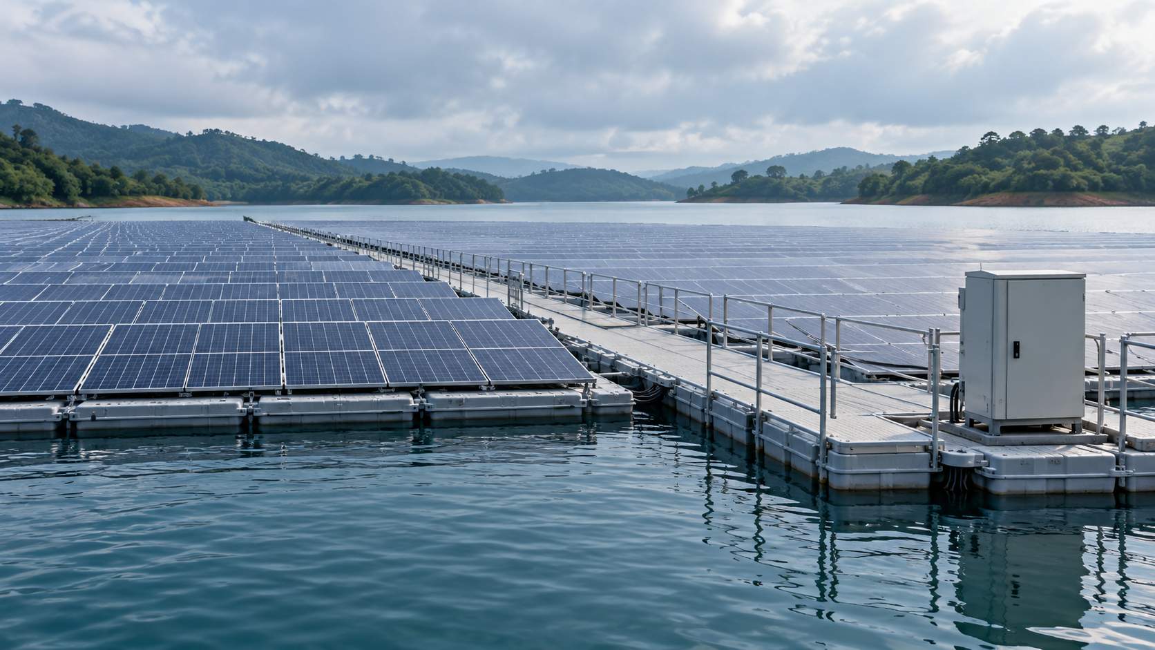
Describe the water exposure
Floating PV layouts vary: some electrical equipment sits on a platform, while other collection points remain on shore. Identify the intended location before selecting an enclosure. Record spray, splash, wave motion, possible temporary inundation, cleaning water, humidity and the highest credible water level from project data.
IEC 60529 defines enclosure IP classifications, but a code alone does not describe every project exposure. If immersion is credible, specify depth, duration, temperature and the complete tested assembly. Confirm whether doors, glands, cable connectors, blanking plugs and field-installed accessories are covered by documented ratings.
- Distinguish above-water platform locations from shore cabinets.
- Document expected and exceptional water levels.
- Do not assume every floating system requires the same IP code.
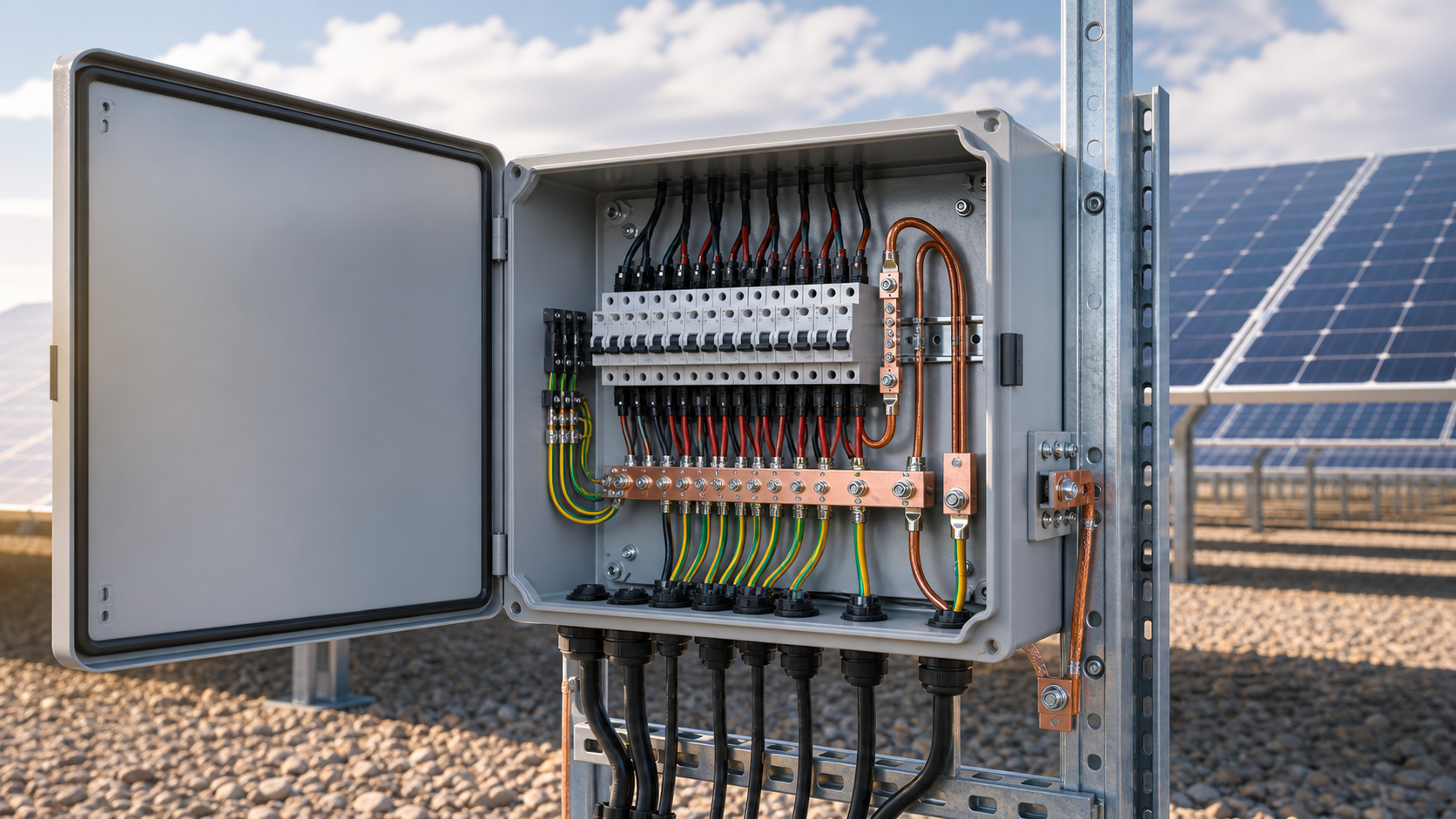
Technical diagram shown at a readable responsive scale.
Select a serviceable mounting location
Keep equipment clear of routine splash and anticipated inundation where the project layout permits. Coordinate the platform, supports and enclosure for expected load, vibration, movement and access. Provide a stable maintenance route and a way to isolate and identify the correct circuit without improvising work over water.
If a shore transition is used, show where the cable leaves the moving structure and how the transition accommodates motion. A mounting point protected from rain can still be difficult to reach or exposed to spray and condensation.
- Show maintenance access and safe working positions on the layout.
- Confirm structural supports and fasteners for platform movement.
- Agree isolation and emergency-response methods with the operator.
Manage cable entry and movement
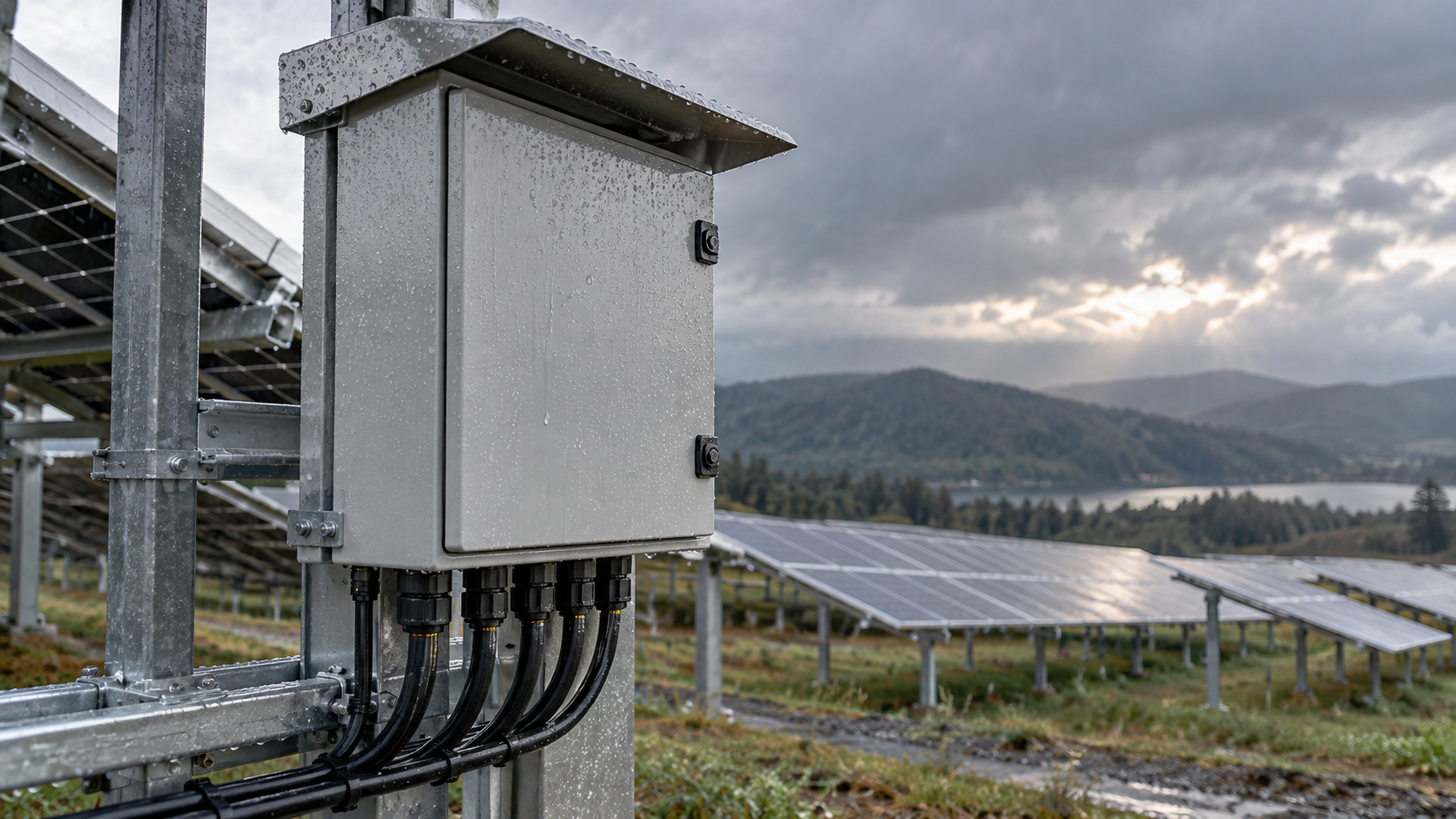
Cable entry is a system interface, not just a gland choice. Specify conductor type, bend radius, strain relief, connector compatibility and routing around moving floats. Keep unused openings sealed with accessories approved for the installed enclosure. Review cable support under the movement, tension and environmental loads expected on the project.
IEC 62548-1 covers PV array topics including DC wiring, protection, switching and earthing. Apply the current project edition with local requirements and the cable, connector and enclosure manufacturers' installation instructions.
- Define movement and support at each float or shore transition.
- Verify glands and connectors against conductor size and enclosure documentation.
- Protect wiring from abrasion, standing water and service traffic.
Technical diagram shown at a readable responsive scale.
Match materials to water chemistry
Freshwater, brackish water and coastal exposure can create different corrosion conditions. Obtain site water or atmospheric data where needed and select compatible enclosure, fastener, support and conductor materials using supplier evidence. Do not assume a stainless grade or coating is suitable for every reservoir or marine environment.
Consider dissimilar-metal interfaces and the details that preserve protective finishes. Document inspection points and replacement parts that maintain the specified environmental performance.
- Record salinity or other site chemistry where it affects material selection.
- Review galvanic compatibility at mounting and bonding interfaces.
- Include seals, fasteners and cable accessories in the material check.
Design bonding and surge protection
Define the earthing and bonding architecture from the electrical design and platform materials. Water is not a substitute for an engineered protective-conductor path, and the method depends on system topology, local rules and equipment. Show intended bonding points and verify continuity using the approved commissioning method.
Select PV DC surge protective devices from system voltage, exposure assessment and coordinated protection design. IEC 61643-31 specifies requirements and tests for PV DC SPDs; use the standard and current project documents rather than treating a water location as a complete SPD specification.
- Identify exposed conductive parts and intended bonds.
- Confirm the grounding method with the system engineer and local rules.
- Record SPD ratings and field inspection method.
Verify thermal and maintenance conditions
A tightly sealed enclosure can limit heat transfer and may experience internal condensation cycles. Check component losses, ambient range, solar exposure and mounting orientation. Verify that the enclosure and components remain within their documented limits; do not infer thermal suitability from an IP code.
Prepare an inspection plan for seals, cable supports, corrosion, moisture indicators and device status where fitted. Set access frequency from site exposure and manufacturer instructions, and retain records of enclosure changes and maintenance.
- Check component temperature limits in the final enclosure.
- Define inspection responsibilities and safe access conditions.
- Separate communication alarms from confirmed electrical faults.
General engineering information, not a project design, product certificate, code determination or safe-work procedure. Verify final ratings, installation, protection coordination and local requirements against current standards, exact manufacturer documentation and the approved project design.
Frequently asked questions
Does every floating PV combiner box need IP68?
No universal enclosure rating applies to every site. Choose from the actual location and specified water exposure. If immersion is possible, verify depth, duration and complete assembly against test documentation.
Can an IP code alone prove suitability for a floating platform?
No. An enclosure code does not establish corrosion resistance, mechanical support, cable movement, thermal performance or safe access. Review each condition against project and manufacturer evidence.
Is reservoir water a suitable grounding path?
Do not assume that. The bonding and protective-conductor method must come from the approved electrical design and local requirements.
How should cables cross between a floating array and shore?
Specify cable, support, strain relief, bend radius and transition for expected movement and environmental loads, then check against the component manufacturers' instructions.
Does a sealed enclosure prevent overheating?
No. Ingress protection and heat dissipation are separate checks. Verify internal losses and temperatures in the exact enclosure and mounting arrangement.
Review the project inputs
Share the system voltage, circuit schedule, installation location and site conditions so the equipment discussion can be checked against approved project documentation.
Discuss a projectContinue learning
Explore related technical guidance in Solar PV.
Prepared from the approved Period 09 source package with technical claims revised to retain project-specific and manufacturer-specific limits. Official source pages describe scope; they do not certify a NEUTRON product configuration or a customer installation.