
Why sag events stop continuous-process plants
The smelter in this case had suffered several sag events over two summer months, and the worst one stopped the line for over two hours: dozens of drive units alarmed and tripped, output fell, product quality suffered and the financial impact was significant. Sag damage is not a nuisance cost — for a continuous plant it is a direct production loss, which is why the tolerable dip depth and duration must be evaluated against the site, the grid load behavior and the actual event waveform rather than a generic rule.
Reading the sag waveform: 46 ms of misery
The customer reported a 46 ms sag, but the recorded waveform showed the dip actually began earlier and recovery finished later, so the true event was longer; the retained voltage fell to about 40% (a 60% dip depth). The rapid voltage fall and the short dip period pointed to an external line fault: a temporary short circuit drew current to the fault point, dragging the station bus down quickly. Because no fast transfer was installed at the time, the bus was fully exposed to the external fault and the sag waveform was steep and short.
Technical diagram shown at a readable responsive scale.
The fast-transfer concept
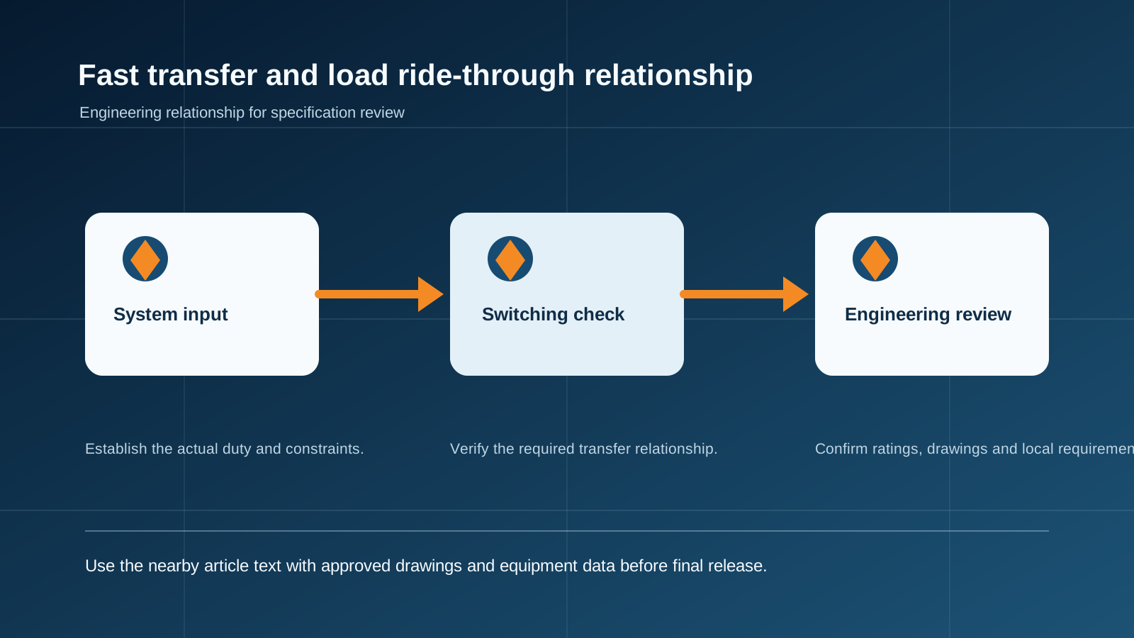
A fast transfer scheme reacts before the sag becomes catastrophic. The transfer controller continuously samples the incoming feeds, the bus voltage and the feed current. When the internal model confirms a fault event, the controller trips the faulty incoming breaker within 3–4 ms, then verifies amplitude, phase and frequency on both sides of the closing point and closes the alternate path with a disturbance-free, impact-free changeover. Cutting the faulty feed early slows the bus decay, keeps the residual voltage above the critical threshold longer, and widens the reliable switching window.
Supply-side remedy: the fast-transfer cabinet
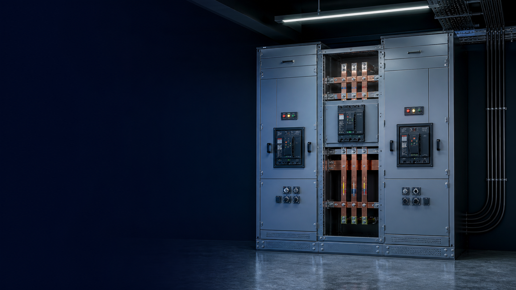
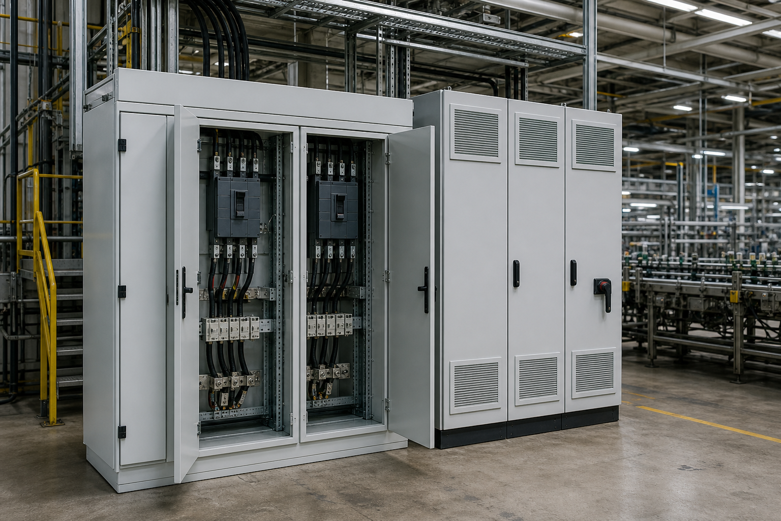
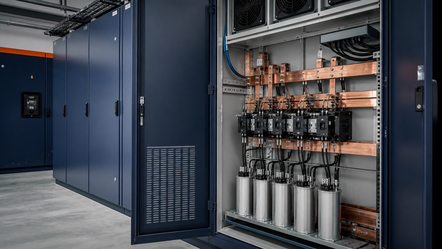
The supply-side installation was a medium/low-voltage disturbance-free fast-transfer cabinet built around a dedicated transfer controller. Its job is to isolate the station bus from external faults and transfer the load to the healthy feed without stopping motors or drives. Safety is built in: by judging voltage amplitude and current flow direction, the controller distinguishes internal from external faults — on an internal fault it blocks the transfer and issues a blocking signal so a bad changeover cannot enlarge the fault.
Three startup modes that matter in the field
The controller supports several startup strategies; the site selected three primary modes, tuned with simulation and commissioning data:
Protection startup: when an upstream main-protection relay operates, the fast-transfer device starts switching immediately.
Loss-of-voltage startup: when the bus voltage falls below the set threshold, the device starts the transfer; the set point is optimized from simulation and field data.
Abnormal frequency/voltage startup: when the incoming feed disappears and the load island-runs, the device detects the bus frequency drifting from nominal and starts the transfer.
Load-side remedy: dip ride-through modules for VFDs
Most sag-sensitive equipment on site was variable-frequency drives (VFDs). As a second line of defense, ride-through (motor restart) modules were added at the load side for three auxiliary oil pumps of the blowers. The module monitors the contactor state and the run signal, and ties into the DCS:
Run-signal output: keeps the DCS run signal closed during the event so the DCS does not issue a stop command when the contactor opens.
Reset signal: releases the VFD fault latch before restart is attempted.
Alarm output: blocks a false VFD fault alarm from reaching the DCS.
When the sag occurs, the contactor drops, the module blocks the fault-latch signal, an internal supercapacitor powers the unit, and if the supply recovers within the programmed window (up to about 9 seconds), the module resets the drive fault and restarts the motor automatically, returning the process to its pre-event state.
System topology: dual-feed, single bus, tie breaker
The plant uses a dual-feed arrangement with a single bus divided into two sections. Under normal operation the two incoming breakers are closed and the tie breaker is open — the sections run separately. On a sag or loss of one section, the fast-transfer controller trips the faulty incoming breaker and closes the tie breaker, so one healthy feed carries the whole load and motors and drives never stop. When the preferred feed returns, the controller tracks amplitude, frequency and phase and returns to the separate-running arrangement, manually or automatically.
A practical specification checklist
Transfer speed vs drive tolerance: VFD undervoltage trip thresholds are typically around 75% with a delay setting; a 30–40 ms changeover meets the no-stop requirement for most drives.
Internal/external fault discrimination: require the controller to block transfer on internal faults and issue a blocking signal.
Startup modes: match the startup strategy (protection / loss-of-voltage / frequency abnormal) to the actual site fault pattern.
Load-side backup: add ride-through modules on the most sensitive drives so even extreme events recover automatically.
Restoration path: verify the controller can track the recovered feed and return the bus to normal operation without a second disturbance.
This guide supports initial technical discussion only. Final ratings, standards, protection coordination, drawings and configuration must be confirmed for the actual project requirement.
Frequently asked questions
What causes voltage sags in industrial plants?
Most sags come from external line faults — a temporary short circuit draws current to the fault point and drags the station bus down quickly. The dip depth and duration depend on grid behavior and the fault location.
How fast does a fast transfer operate?
A fast-transfer controller detects the event within about 3–4 ms, trips the faulty incoming breaker, verifies amplitude, phase and frequency, and closes the alternate path — a disturbance-free changeover fast enough for VFD-driven loads.
What is the difference between supply-side and load-side sag protection?
Supply-side fast transfer removes the faulty feed quickly and changes to the healthy feed to protect the whole bus. Load-side ride-through modules keep individual sensitive drives (contactors and VFD fault logic) alive and restart them if the event persists.
Can VFDs ride through a sag without stopping?
With a fast transfer completing in 30–40 ms, most VFDs stay running because their undervoltage trip threshold (~75% with delay) is not crossed long enough. For extreme events, load-side modules reset the drive fault and auto-restart within a programmed window.
What does blocking on internal faults mean?
The controller distinguishes internal from external faults. On an internal fault it blocks the transfer and issues a blocking signal, so the changeover cannot worsen the fault.
Discuss Your Transfer-Switch Requirement
Share the supply arrangement, load duty, operating environment and document requirement so the relevant configuration can be reviewed before quotation.
Discuss a projectContinue learning
Explore related technical guidance in Power Distribution.
Technical note: this article is published from the approved 2026-08-24 source package. Confirm the final electrical design, local code basis and manufacturer documentation for the actual project.