
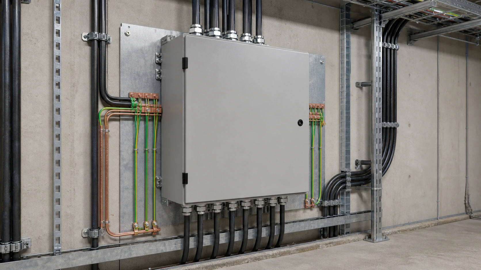
What an ATS does in the one-line diagram
An automatic transfer switch monitors a normal incomer, detects an abnormal condition and transfers the load to a standby incomer such as a generator, second utility feed or UPS. When the normal source returns and stabilizes, it transfers back according to the programmed logic.
- Identify the normal source, standby source, load terminals and any generator-start interface.
- Confirm whether the product is a split controller system, integrated ATSE or compact modular ATS.
- Use the manufacturer's terminal diagram and approved project one-line as the controlling documents.
Pre-installation: ratings, site and enclosure checks
Correcting an ATS rating error after the panel is wired is expensive. Confirm the actual maximum demand, utilization category, voltage, frequency, short-circuit withstand, pole count, mechanical envelope, ambient range and altitude before installation.
- Size on maximum demand with headroom, not only on the incoming breaker frame.
- Check AC-31, AC-33 or AC-35 duty as applicable to the load.
- Confirm clearances, door swing, cable bending space and enclosure protection.
- Verify that the standby source and upstream protection are compatible with the ATS duty.
Tools, PPE and safe isolation
Use calibrated torque tools, insulated hand tools, correctly sized lugs and crimp tools, a two-pole voltage tester, proving unit, insulation tester, continuity tester, clamp meter and phase-rotation meter as required by the approved method statement.
- Obtain the permit and confirm both incomers on the one-line diagram.
- Open and lock off the normal and standby incomers, including generator auto-start control.
- Isolate separately fed controller and auxiliary supplies.
- Prove the tester, prove dead at every conductor including neutral, then re-prove the tester.
- Apply earths and caution labels where the local rules require them.
Step-by-step wiring procedure
Mount the switch in the orientation shown on the drawing, identify the normal and standby terminals from the product diagram, and keep power and control wiring arranged so the mechanism can travel through both positions.
- Terminate the normal incomer with correct phase rotation and torque.
- Terminate the standby incomer and verify that its phase rotation matches the normal source.
- Terminate load, neutral and earth according to the approved neutral scheme.
- Wire source sensing, generator start, alarm and position interfaces as required.
- Dress, ferrule and label conductors, then check that no wire fouls the mechanism.
- Before energization, repeat insulation, earth-continuity and torque checks and manually operate the switch while isolated.
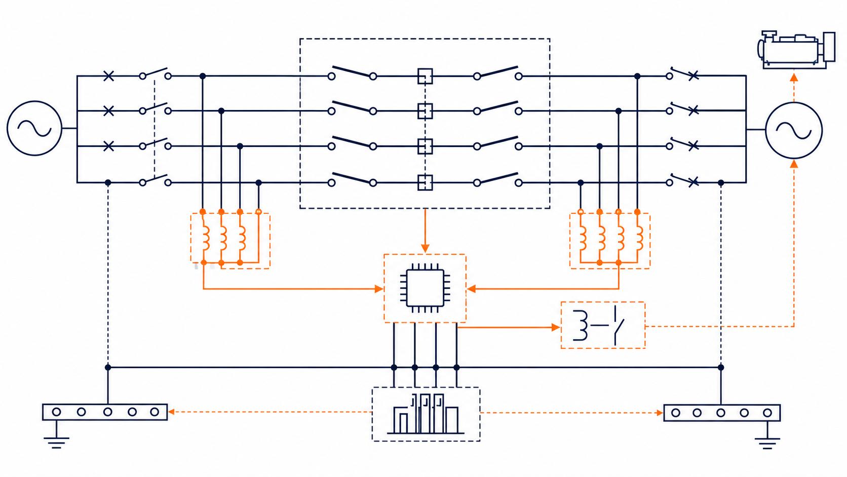
Technical diagram shown at a readable responsive scale.
Neutral handling: 3-pole versus 4-pole
The pole decision comes from the earthing arrangement, not preference. A 3-pole ATS leaves a common neutral solid. A 4-pole ATS transfers the neutral with the phases where the sources have separate neutral-earth bonds or the approved design requires switched neutral.
- Use 3-pole only when both incomers share the same earthing reference and a solid neutral is permitted.
- Use 4-pole for separately derived and separately earthed standby supplies and where required by the approved design.
- Check any downstream residual-current protection because parallel neutral paths can cause nuisance tripping or defeat the intended protection.
Controller settings and timers
Default settings rarely suit the actual site. Record every setting in the commissioning file and set the undervoltage, overvoltage, fault delay, transfer dwell, generator start delay, return delay, cool-down and phase-loss functions deliberately.
| Setting | Purpose | Typical basis |
|---|---|---|
| Undervoltage | Detect loss or sag | Project threshold below rated voltage |
| Transfer dwell | Allow motor residual voltage to decay | Project and product-specific delay |
| Generator start delay | Ignore momentary dips | Generator and load response |
| Return delay | Confirm source stability | Long enough to avoid repeated cycling |
| Cool-down | Run generator off-load before shutdown | Generator manufacturer's recommendation |
Commissioning and functional testing
Commissioning should prove the electrical behavior, mechanical interlock, timing, signaling and documentation rather than merely showing that the cabinet powers up.
- Energize and verify each incomer separately, including phase rotation.
- Prove that the two incomers cannot close simultaneously.
- Simulate loss of the normal source and check generator start, transfer timing and load energization.
- Restore the normal source and confirm the return delay, retransfer and generator cool-down.
- Repeat with design load, then verify manual, emergency, remote and alarm functions.
- Record settings, test results, torque values, insulation readings and the as-built diagram.
Common installation errors
The most damaging errors are mismatched phase rotation, the wrong pole count, sizing from the breaker frame instead of the load, leaving an auxiliary supply live, routing control cables beside power cables and failing to exercise the ATS periodically.
- Verify phase rotation on both incomers with a rotation meter.
- Do not assume the neutral arrangement from the ATS label; confirm the earthing design.
- Use separate containment for sensing and communications where required.
- Schedule documented off-load and on-load exercise tests at the interval required by the facility plan.
This guide does not replace a permit-to-work, local electrical rules, the product manual, the approved wiring diagram or commissioning by an authorized person.
Frequently asked questions
Can I install an ATS myself?
Only if you are a competent, authorized person working under the applicable safety process with suitable test instruments and PPE. Many jurisdictions also require licensed electrical work and formal inspection.
Do I need a 3-pole or 4-pole ATS?
Use the approved earthing arrangement. A 4-pole switched-neutral ATS is commonly required where the sources are separately derived or separately bonded; a 3-pole switch is suitable only where a solid neutral is appropriate.
How do I verify the ATS wiring?
Check terminal identification, phase rotation, neutral and earth continuity, insulation resistance, torque, mechanical interlock, controller sensing, generator start and alarm interfaces before energization.
Why does an ATS transfer back and forth?
The return delay may be too short for the stability of the normal supply, or the sensing thresholds may not match the source. Review the source condition and settings instead of repeatedly cycling the switch.
How often should an ATS be tested?
Use the facility maintenance plan, product instructions and local requirements. A documented periodic exercise should verify transfer, return, interlocking and alarms under the appropriate load conditions.
Review the ATS Before Wiring
Send the one-line diagram, load schedule, earthing arrangement and prospective fault current so the ATS rating, pole count, controller settings and enclosure can be checked before installation.
Request a quoteContinue learning
Explore related technical guidance in Power Distribution.
Safety note: all ratings, wiring arrangements and commissioning intervals must be confirmed for the actual ATS, installation and destination market.