
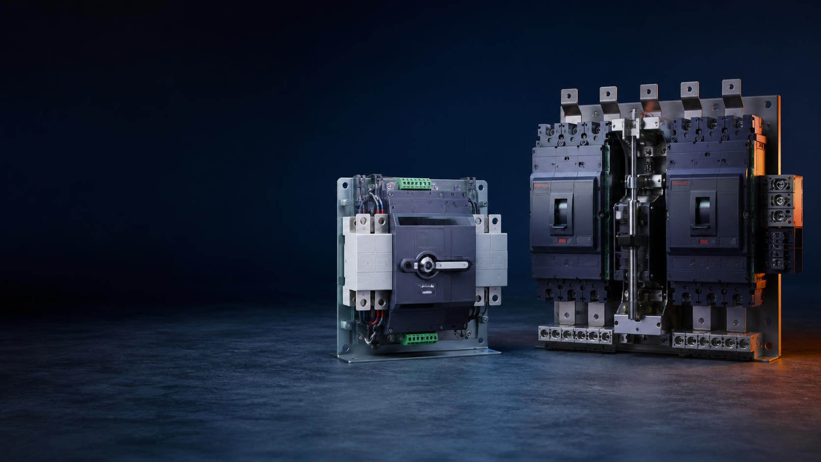
Why the transfer switch class decision matters
Facilities such as elevators, fire protection systems, surveillance equipment and banking power supplies cannot tolerate a long outage. A transfer switch provides one preferred feed and one standby feed: when the preferred side fails, the switch automatically connects the load to the standby side. In small systems the standby can be a generator set. The class of the switching device — not just its rated current — determines whether the transfer holds up under fault conditions, whether it switches fast enough for the load, and whether the installation satisfies the local low-voltage distribution code.
PC-class and CB-class at a glance
PC-class: a transfer switch able to make and carry normal and fault currents, but not intended to interrupt short-circuit currents. Its withstand is verified by the short-time withstand current (lcw) and short-circuit making capacity (lcm).
CB-class: a transfer switch fitted with overcurrent releases whose main contacts can make and break short-circuit currents — in practice two circuit breakers form the switching body.
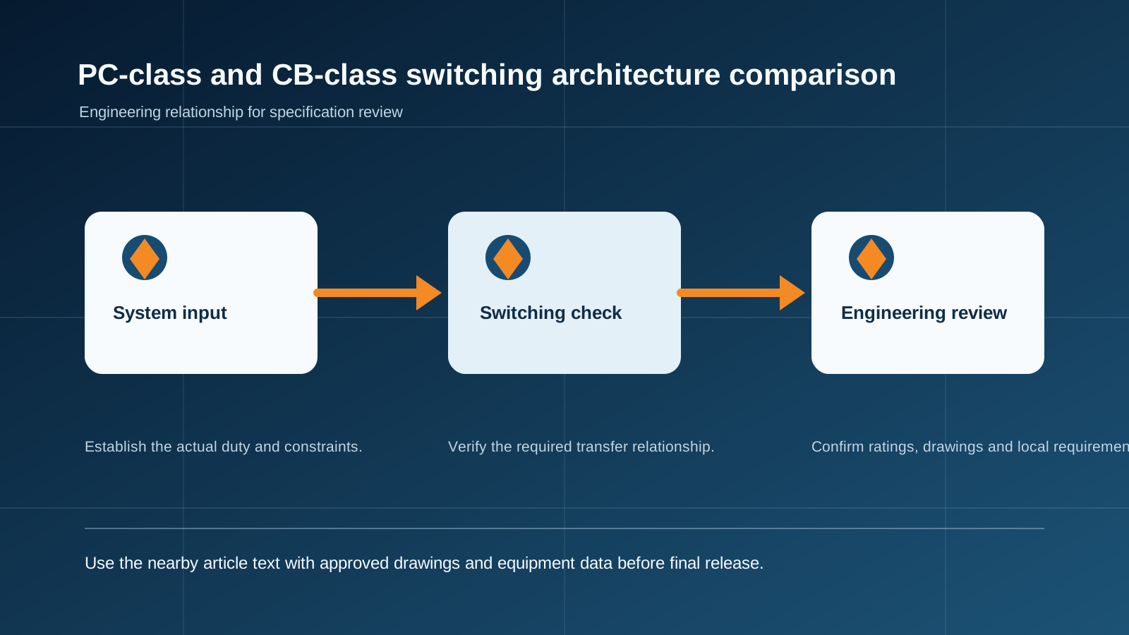
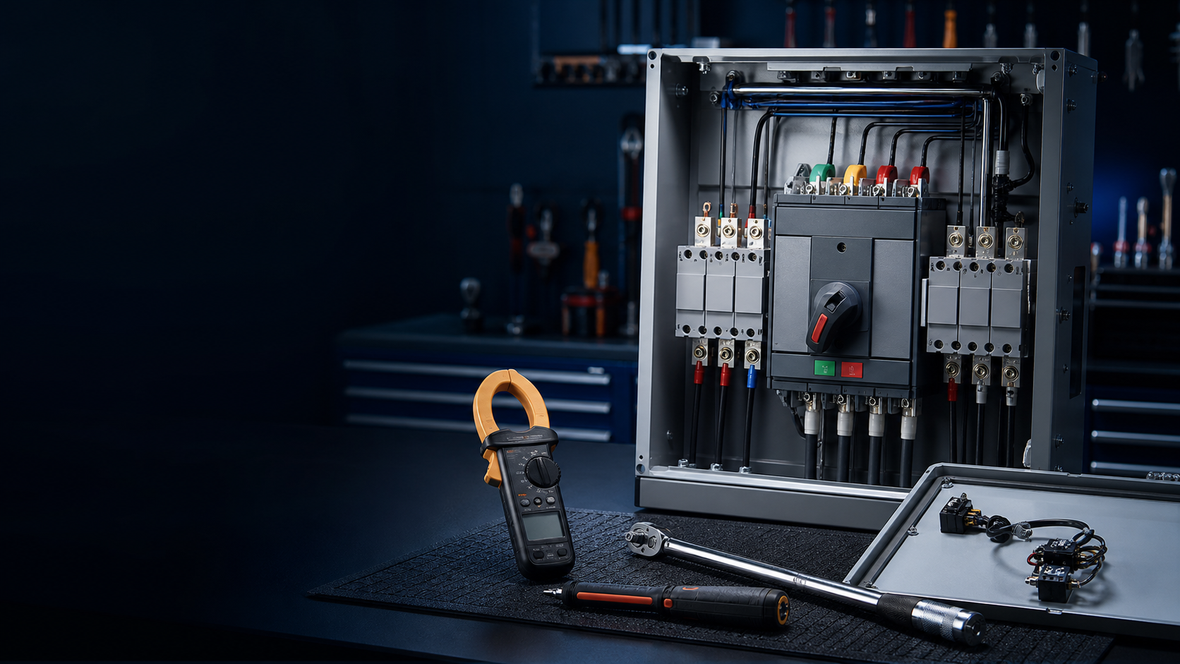
Technical diagram shown at a readable responsive scale.
Mechanism design: why PC-class is more reliable
CB-class units are built from two circuit breakers. A breaker is designed to interrupt arcs, so its mechanism must trip fast; that fast-trip design introduces the risk of latch slip and unreliable re-closure. A PC-class mechanism carries no short-circuit interruption duty, uses a simpler mechanical-plus-electronic transfer lock, and has roughly half the moving parts of a breaker-based unit. For this reason PC-class reliability is generally higher — the same relationship as a load-break switch versus a circuit breaker of similar rating.
CB-class body = two MCCBs, the most complex transfer-switch architecture in common use.
PC-class avoids latch-slip and re-closure concerns, which matters when the standby path sits idle for months.
Clearance, creepage and the two-supply overlap problem
During transfer, the two feeds can momentarily overlap or interact. PC-class designs take this into account: their clearance and creepage distances are typically 180% and 150% of a comparable breaker (standard requirements), giving a safer dielectric envelope around the switching gap. Breaker-based bodies follow circuit-breaker clearance rules, which are tighter because a breaker is designed to clear faults, not to sit between two live feeds.
Contact materials and the oxidation risk
Breaker contacts often pair silver-tungsten or silver-tungsten-carbide to support arc interruption. These materials oxidize more readily, and a standby contact left exposed for a long period can build a stubborn oxide film. When that contact finally carries load, the extra resistance drives temperature up sharply and can destroy the switch or, in severe cases, cause an internal fault. PC-class transfer switches use contact materials and pressure design chosen for the standby position: higher contact pressure keeps the contacts from being blown apart and from welding under overload (the design covers overloads of 20 times rated current and above).
Transfer time decides where each class fits
Transfer time differs significantly between the classes, and for some loads it is the deciding factor. Emergency evacuation lighting, for example, requires the shortest possible changeover and in practice can only be served by a PC-class unit.
Emergency / evacuation lighting: PC-class only — switching time is the hard requirement.
Elevators, security and monitoring: PC-class or CB-class depending on the tolerated interruption window.
General power loads: either class; decide on reliability budget, fault duty and maintenance policy.
Selecting for fire and life-safety loads
Low-voltage distribution design codes (e.g. GB 50054) require that a circuit whose disconnection under overload would cause serious consequences must not be interrupted by overload protection; overload may only be signaled. Where a CB-class transfer switch serves fire-fighting loads, it must be built from circuit breakers providing short-circuit protection only. In practice, fire-fighting loads are usually served by PC-class units to avoid the complexity and to meet the transfer-time and reliability demands.
A common misunderstanding: the short-circuit breaking function of a transfer switch protects the downstream circuit and equipment, not the switch itself. A PC-class unit without short-circuit interruption still performs its transfer function correctly; the designer decides separately whether the system needs an upstream breaker.
Isolation, maintenance and a five-point specification checklist
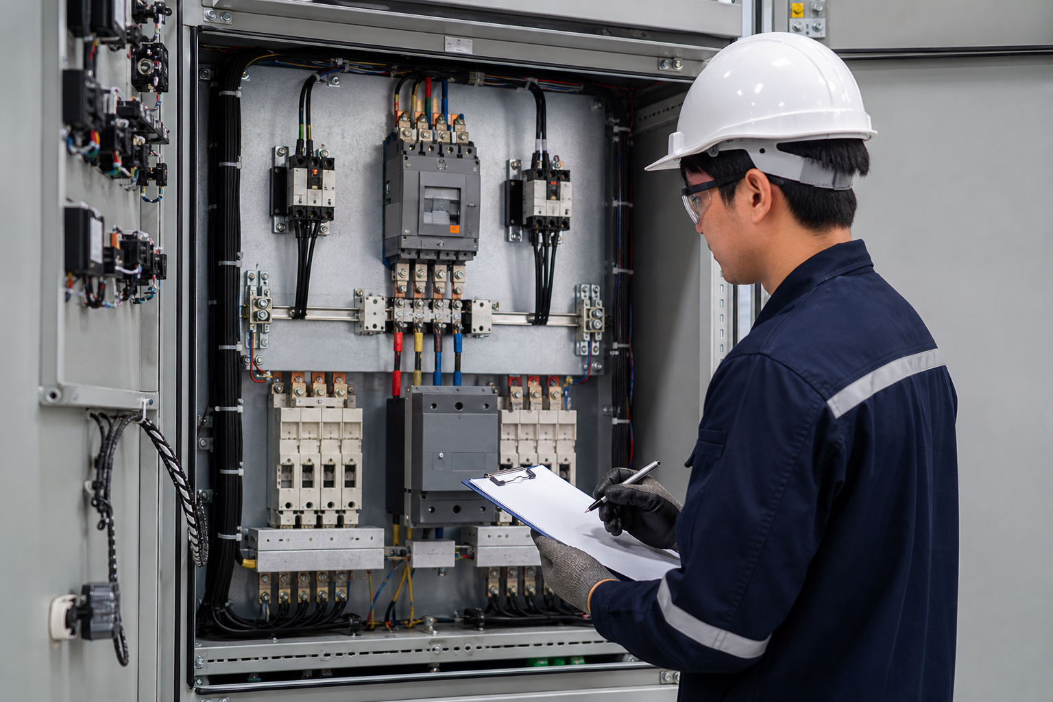
A transfer switch should offer isolation for maintenance. When the unit has no built-in isolating function, the design must add an isolating switch upstream. In industrial systems the number of isolating switches should be controlled — they take space, add cost and lower reliability; in residential floors they are generally unnecessary.
Five specification points before you order:
PC-class rating: rated current no less than 125% of the calculated (design) current, and withstand of the expected short-circuit current (lcw / lcm).
CB-class rating: select the breaker parameters as you would select a circuit breaker, and verify the exact breaker model inside the unit against the installation duty — many designs only list model, current and poles, ignoring the breaker specification.
Fire-fighting loads: prefer PC-class; if CB-class is used, specify short-circuit-only MCCBs.
Fast-transfer loads (evacuation lighting): PC-class.
Isolation: add an upstream isolating switch when the unit has no isolation function; for fire-fighting supply avoid transfer switches with an intermediate OFF (zero) position.
This guide supports initial technical discussion only. Final ratings, standards, protection coordination, drawings and configuration must be confirmed for the actual project requirement.
Frequently asked questions
Can a PC-class ATS break short-circuit current?
No. A PC-class unit is designed to make and carry normal and fault currents but not to interrupt short-circuit currents. Short-circuit protection must be provided by an upstream or separately integrated circuit breaker.
Why is PC-class recommended for fire-fighting loads?
Fire-fighting loads must keep running even under overload, so overload protection must not disconnect the circuit. PC-class units have no overcurrent release and provide the reliability and transfer time these loads require.
Which class should be used for emergency evacuation lighting?
PC-class. Evacuation lighting demands a very short transfer time, and PC-class mechanisms switch faster than breaker-based CB-class bodies.
Does a PC-class ATS need an external circuit breaker?
It depends on the system design. The PC-class unit has no short-circuit protection of its own, so the designer must decide whether the circuit requires an additional breaker upstream.
What does the 125% rating rule mean in practice?
For PC-class units, the rated current should be no less than 125% of the calculated design current, leaving headroom for overload and continuous duty.
Discuss Your Transfer-Switch Requirement
Share the supply arrangement, load duty, operating environment and document requirement so the relevant configuration can be reviewed before quotation.
Discuss a projectContinue learning
Explore related technical guidance in Power Distribution.
Technical note: this article is published from the approved 2026-08-24 source package. Confirm the final electrical design, local code basis and manufacturer documentation for the actual project.