
ATSE as a dedicated low-voltage category
The standard defines an ATSE as an assembly of one or more transfer switching devices and the other apparatus needed to detect the state of the supply circuits and to transfer one or more load circuits from one supply to another automatically. Two classes are defined: PC-class — makes and carries, but is not intended to break short-circuit currents; and CB-class — fitted with overcurrent releases whose main contacts can make and break short-circuit currents.
Certification matters: ATSE has not been brought under compulsory certification in China, so the only objective evidence that a product conforms to the GB/T 14048.11 standard is CQC certification. The type tests for PC-class and CB-class units are different, and their CQC certificates cannot replace one another. A controller is a mandatory part of an ATSE — it continuously monitors both supplies and transfers on phase loss, under- or overvoltage, or frequency deviation — and it is this controller that distinguishes an ATSE from other low-voltage switchgear.
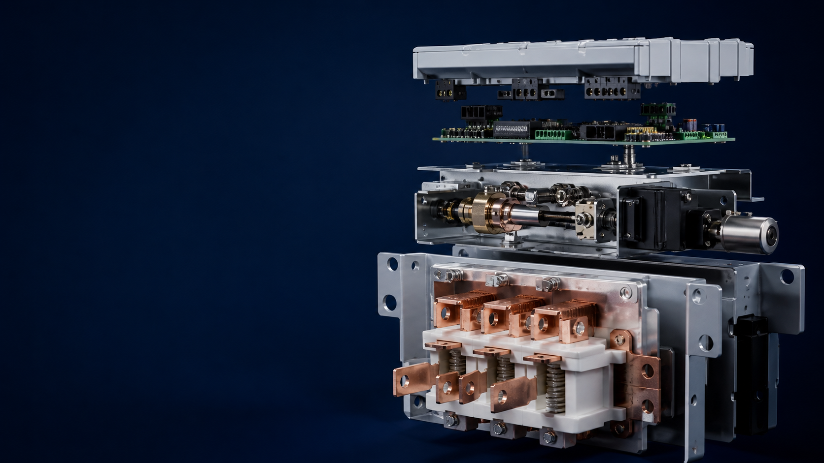
Anatomy: body, drive and controller
An ATSE consists of three parts that must advance together — a weakness in any one is a weakness of the whole:
Switch body: contact structure and material, moving/fixed contact connection, contact pressure, synchronization, overtravel, opening speed and arc-extinguishing method.
Drive / hold mechanism: the transmission that closes and opens the contacts — electromagnetic direct drive (e.g. contactor), excited drive with linkage and mechanical hold, or geared motor drive with mechanical hold.
Controller: from a simple single-phase loss detector to units with parameter detection, field setting, display and communication interfaces.
A unit that is technically advanced and reliable must reach the appropriate level in all three parts. When comparing products, judge all three together, not just the electrical ratings.
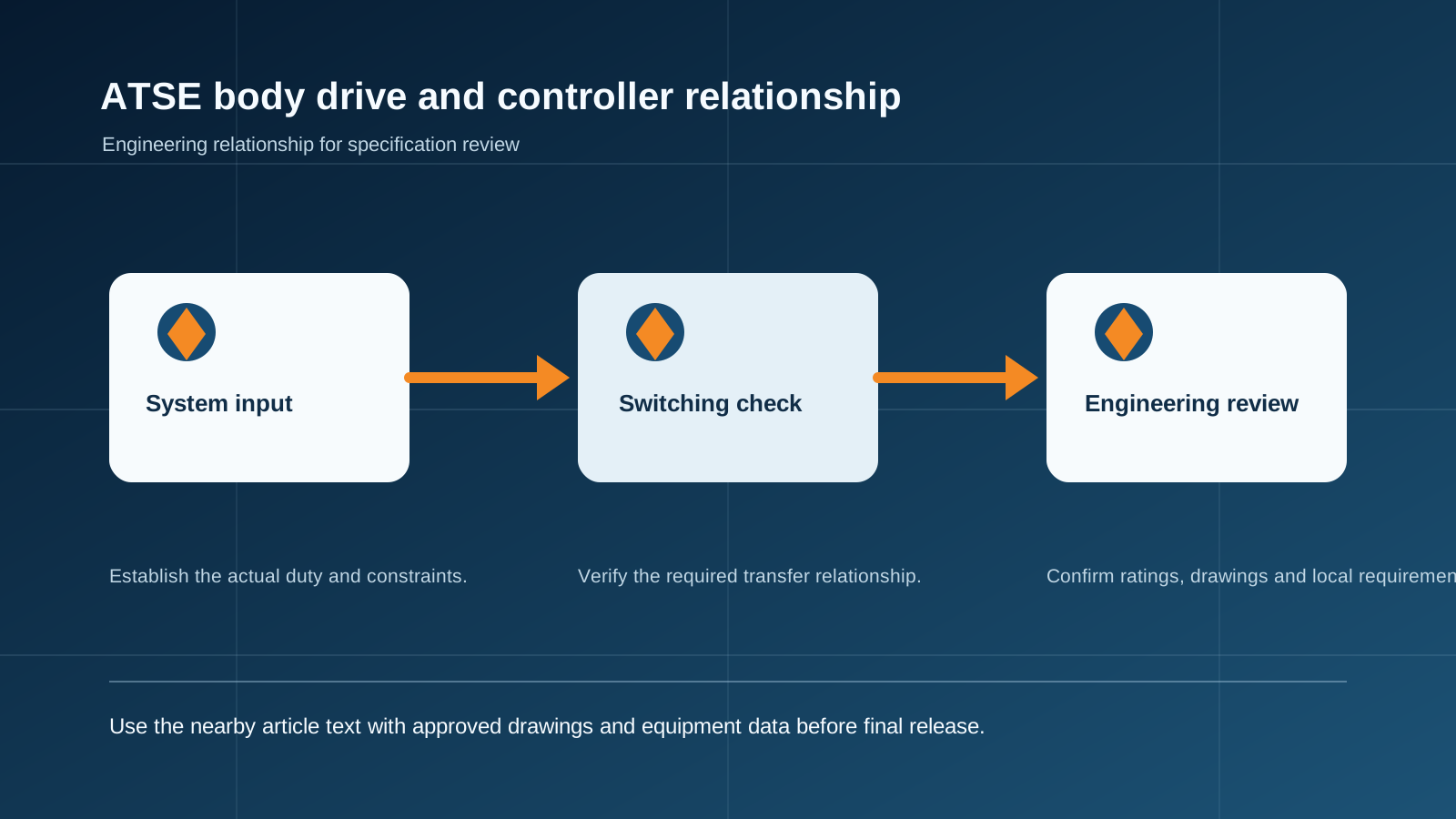
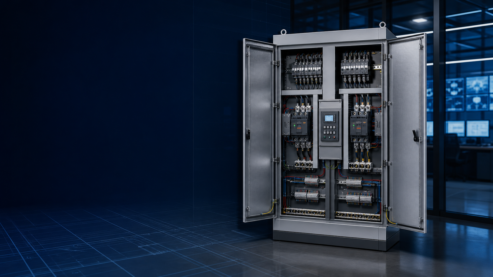
Technical diagram shown at a readable responsive scale.
Switch bodies: standard devices vs purpose-designed
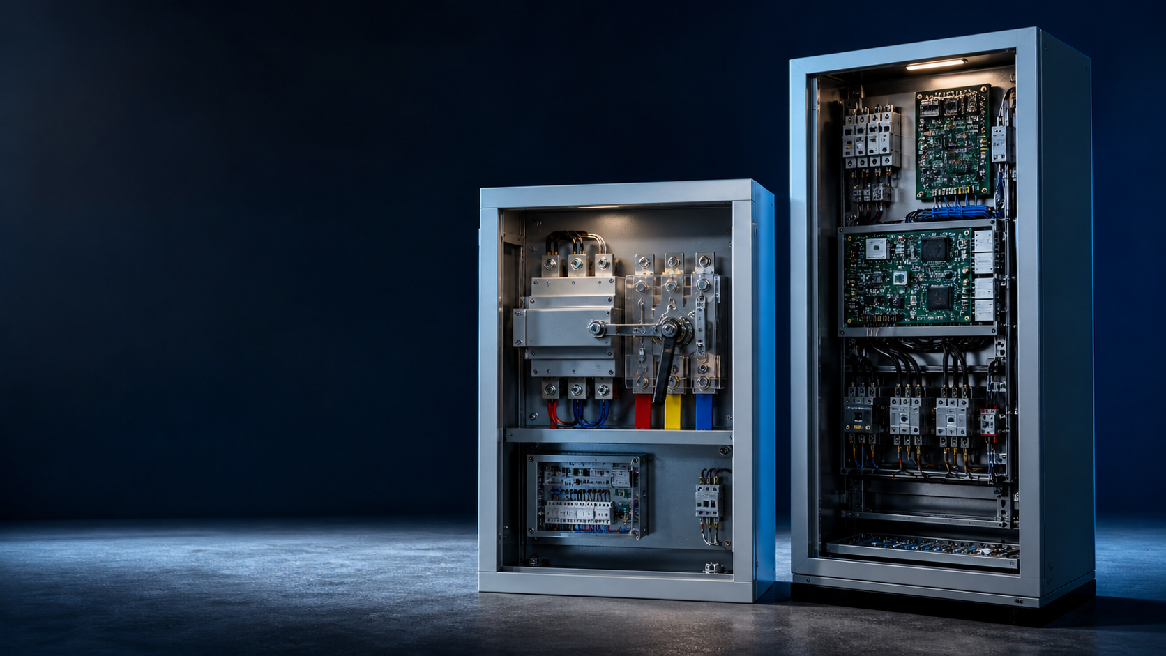
Two body architectures dominate the market. The first uses an existing standard device — a contactor, breaker or isolating switch — as the body; more than 90% of units on the market are built this way. It is cheap, fast to develop and easy to OEM, but the electrical performance is bounded by the chosen body. The second architecture is a purpose-designed body where contact material, pressure, opening speed and arc extinction are engineered for the ATSE duty — the route taken when requirements exceed the generic standard, for example high AC-33 utilization class or high surge-current withstand. This route costs more and takes longer to develop, but it delivers measurably higher performance.
Utilization categories: why AC-33 matters for inductive loads
The choice of body architecture follows the utilization category, which reflects the load type. Fire pumps, fans and elevators are inductive loads and require an ATSE with an AC-33 utilization category (AC-33B at minimum). Meeting AC-33 demands three things: special silver-alloy contact material, a fast opening speed (above 0.5 m/s), and a dedicated arc-extinguishing device. A body built with copper contacts, motor drive with slow opening and no dedicated arc control will struggle to pass a genuine AC-33 type test together with the mechanical and electrical life requirements of the standard.
Drive and hold mechanisms: the speed trade-off
Because the body architecture differs, the drive mechanism differs too. Units built on breakers or isolating switches use a geared motor with linkage, mechanical interlock and mechanical hold — no power needed to stay in position, but transfer is slow: for a 100 A class unit, one second or more can pass between the controller command and the faulted feed opening. Purpose-designed units use excited drive with linkage, mechanical hold and structural interlock; the contacts separate fast — above 0.75 m/s for units up to 100 A — and the faulted feed opens in roughly 30 ms. For loads sensitive to a lost phase, the fast-opening excited design is the safer choice.
The controller: reliability’s weakest link
The controller is the only part that works continuously, and in field service most ATSE faults are controller faults — yet buyers and even some manufacturers focus on electrical performance and overlook it. Design, manufacture and testing of the controller must be strictly controlled. Practical requirements include:
Field-settable transfer time, so that the transfer sequence of multiple ATSE levels in one system can be coordinated.
Communication interfaces that genuinely work — a hardware port alone is not enough; the unit must deliver logged reports the host system can read.
External (replaceable) controller design, so a failed controller can be swapped without dismantling the switch — important because controller failure is the most common field fault.
Selection rules that prevent field failures
Certification first: choose a product with CQC certification per GB/T 14048.11 — the only objective conformance evidence available.
PC-class for high-reliability duty: PC-class structure is more reliable than breaker-based CB-class; international specialist ATSE manufacturers supply PC-class only, which corroborates the point.
Decide PC vs CB on reliability and cost, not on the short-circuit function: a PC-class unit with an upstream short-circuit protective device delivers the same protection as CB-class.
Match the front-end protection: the PC-class rated conditional short-circuit current must match the type and parameters of the upstream protective device; otherwise add protection inside the changeover box.
Match the load: inductive loads need AC-33 class — silver-alloy contacts, fast opening and dedicated arc control — or one transfer can destroy the switch.
Plan for serviceability: fast availability of spare units and a replaceable controller are essential, because a failed breaker in a CB-class unit may force a full replacement and a long outage.
A decision checklist for specifiers
Confirm the standard basis (GB/T 14048.11 / IEC 60947-6-1) and CQC certification on the certificate, not the brochure.
Define the utilization category from the actual load (AC-33 for inductive fire-pump, fan and elevator duty).
Choose the body architecture (standard-device or purpose-designed) from the category and the surge-duty requirement.
Verify the faulted-feed opening time against load sensitivity — 30 ms excited drive vs 1 s-plus geared motor.
Check controller features: field-settable time, working communication and external replacement.
Coordinate the front-end protective device with the ATSE rated conditional short-circuit current.
This guide supports initial technical discussion only. Final ratings, standards, protection coordination, drawings and configuration must be confirmed for the actual project requirement.
Frequently asked questions
What standards define ATSE?
The Chinese standard GB/T 14048.11, which parallels IEC 60947-6-1, defines automatic transfer switching equipment, its classes (PC and CB) and its type tests.
What are the three parts of an ATSE?
The switch body (contacts and arc control), the drive/hold mechanism, and the controller that monitors the supplies and commands the transfer.
Why is the AC-33 utilization category important for inductive loads?
Fire pumps, fans and elevators are inductive loads. AC-33 class requires silver-alloy contacts, fast opening above 0.5 m/s and dedicated arc control — without these, one transfer can damage the switch.
PC-class or CB-class — what should drive the choice?
Reliability and cost, not the short-circuit function: a PC-class unit with an upstream short-circuit protective device gives the same protection as CB-class, and its structure is more reliable.
Why is the controller the most failure-prone part?
The controller is the only component that works continuously, so most field faults are controller faults; it should be field-settable, externally replaceable and strictly tested.
Discuss Your Transfer-Switch Requirement
Share the supply arrangement, load duty, operating environment and document requirement so the relevant configuration can be reviewed before quotation.
Discuss a projectContinue learning
Explore related technical guidance in Power Distribution.
Technical note: this article is published from the approved 2026-08-24 source package. Confirm the final electrical design, local code basis and manufacturer documentation for the actual project.