
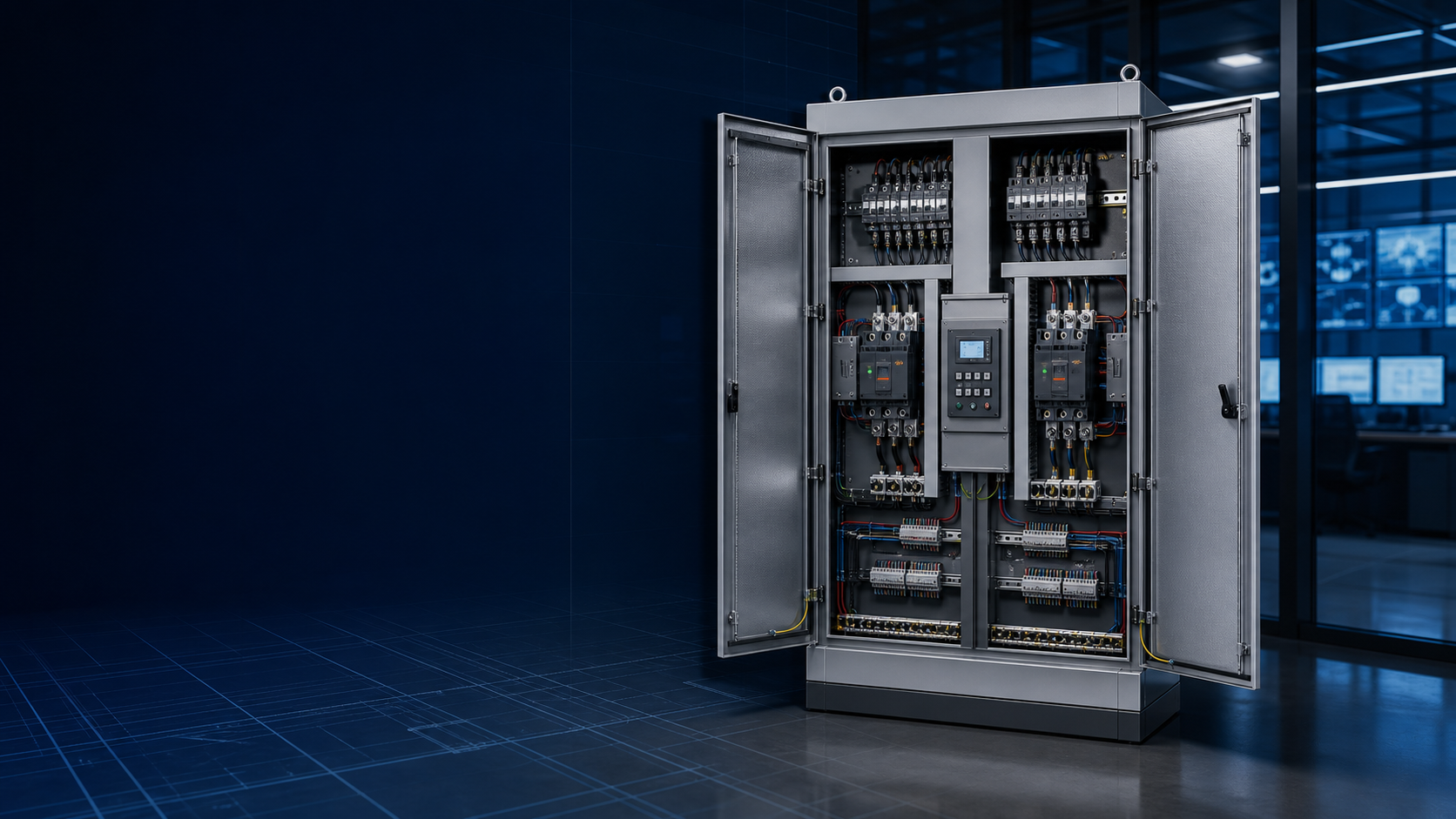
Why railway signal supply is a first-class load
Chinese railway design codes require two supplies for communication and signalling loads, run separately to the equipment or to the low-voltage dual-power transfer device. In current practice, one feed is taken from the station automatic block (auto-close) transformer and another from the continuous (贯通) transformer, both brought to a dual-power changeover box from which the load is fed. The transfer device is the switching point between the two supplies, so its correct selection is critical to reliable power for the signalling system.
Four transfer architectures used in China’s railway projects
Four arrangements have been used in the Chinese engineering sector for dual-power changeover:
Two-contactor type: a simple circuit of two contactors; mechanical interlocking is unreliable, with heating, contact welding and coil burnout — now near-eliminated.
Two-breaker type (CB-class): two breakers with a mechanical interlock and short-circuit/overcurrent protection; interlocking is not fully reliable, mostly used where calculated currents are large.
Excited transfer switch: an excited contactor plus a controller as one unit; interlocking is reliable and the electromagnetic coil drives the switch quickly.
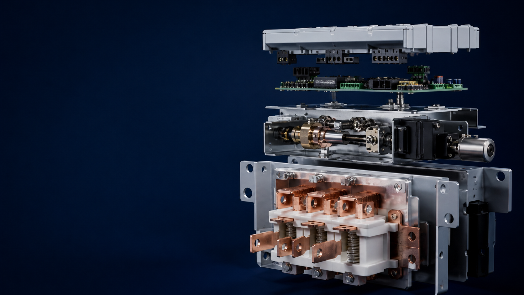
Motor-driven transfer switch (PC-class): based on a load-break switch, motor-driven, smooth and fast, with an intermediate OFF (zero) position option.
The Chinese standard GB/T 14048.11 (paralleling IEC 60947-6-1) classifies transfer switch equipment as PC-class (makes and carries but does not break short-circuit currents) or CB-class (fitted with overcurrent releases whose contacts can make and break short-circuit currents).
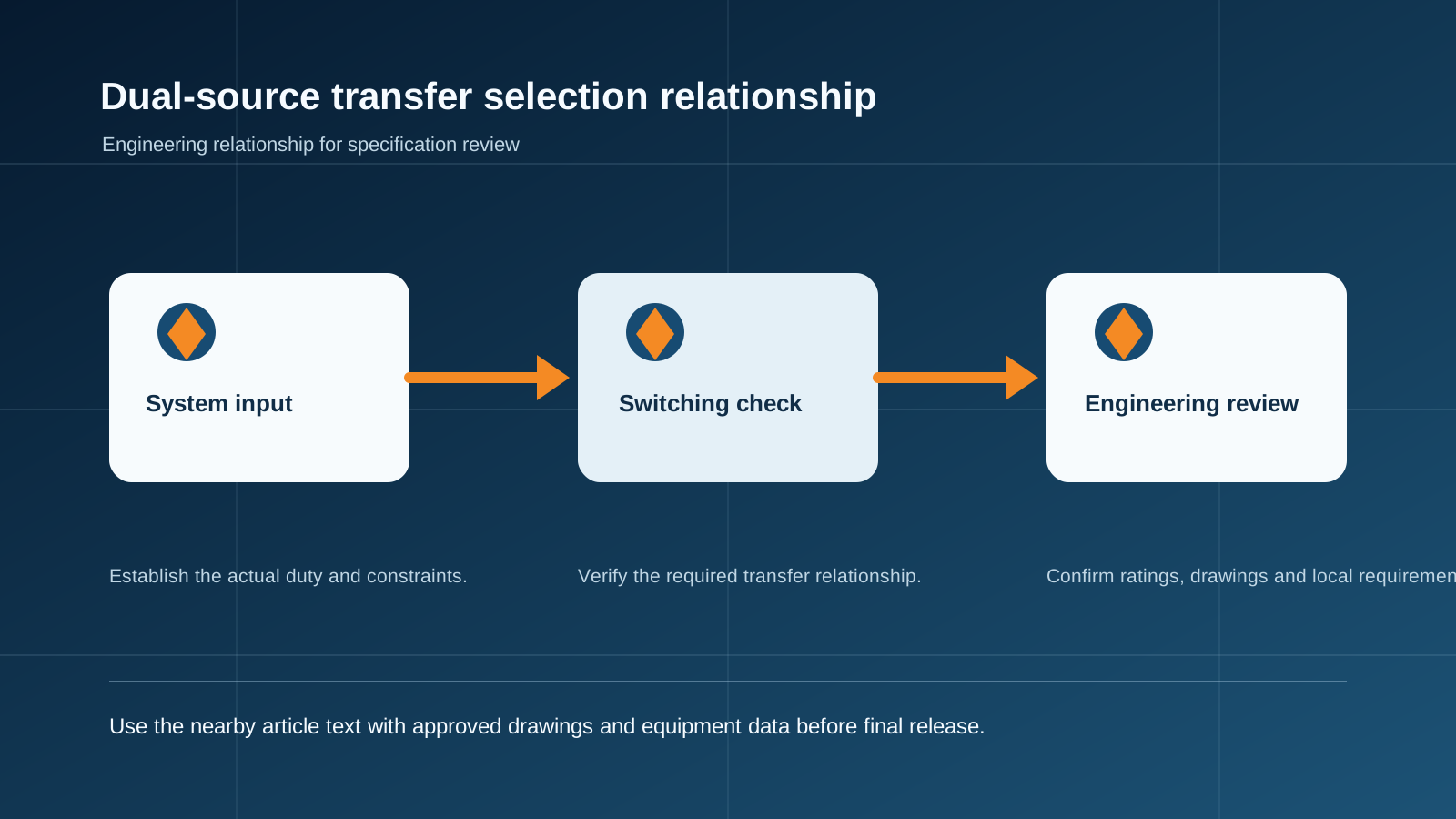
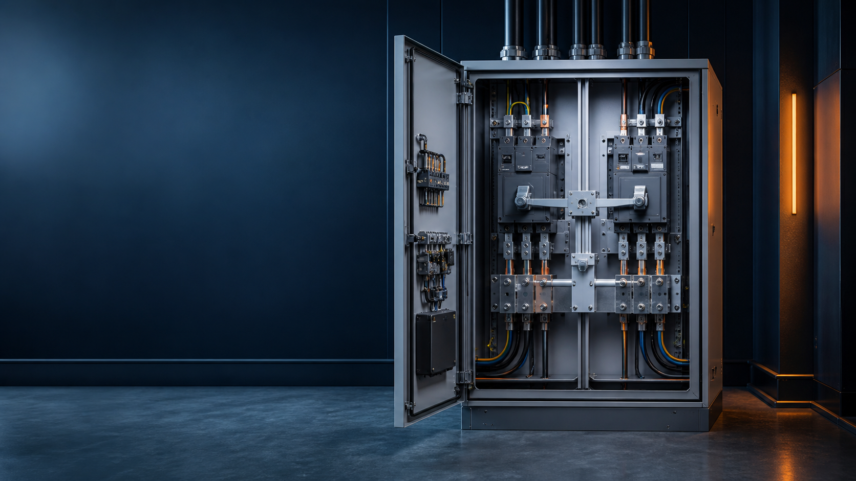
Technical diagram shown at a readable responsive scale.
The five design debates
PC-class or CB-class for the signalling load?
Three-pole or four-pole switching?
Two-position or three-position (with zero) switching?
Can the transfer device itself act as an isolating device?
How is the transfer time determined and coordinated?
PC-class or CB-class for signal loads
CB-class carries thermal-magnetic protection: choose it only when its breaker is selected correctly — the rated breaking current must exceed the expected maximum short-circuit current, and breaker selection must coordinate with upstream and downstream feeders for selectivity. PC-class provides transfer only, with no short-circuit or overload protection; a 250 A and below unit typically withstands 5–12 kA short-time current (1 s). In practice, a CB-class unit in a distribution box needs only an isolating device upstream, while a PC-class unit needs a short-circuit protective device upstream, and outgoing MCBs must coordinate with it.
Two drawbacks of CB-class protection deserve attention: it adds a protection level that must be coordinated with adjacent levels; and because the transfer input is taken from the incoming feed, a breaker tripping on overcurrent while voltage and frequency are normal leaves the load dead without the transfer device operating. For railway signalling, where the two 10 kV feeds are relatively reliable, the transfer-only PC-class approach with upstream protection is usually the safer engineering choice; CB-class keeps an advantage in systems with very large short-circuit capacity.
Three-pole or four-pole switching
For identical supplies with a shared neutral — two public grids, two generator sets — a three-pole switch can be used. A four-pole switch is required when the supplies are of different configurations or when harmonic currents are significant, and between supplies of different capacities: their neutrals carry different zero-sequence voltages, and a closed neutral path creates circulating currents that can damage equipment. In China, the two railway signalling feeds are both 10 kV feeds from the railway traction power distribution, whose upstream is the local public grid — the same supply family — so a three-pole switch is the normal choice unless special conditions apply.
Two-position or three-position transfer
A two-position switch has only two working positions — normal and standby — and transfers faster. A three-position switch adds an intermediate OFF (zero) position, where the contacts sit idle; the zero position exists to pause during transfer for high-inductance or large-motor loads that would otherwise suffer inrush. Because the zero position adds travel, three-position switching is slower. For railway first-class loads, which demand fast transfer and have modest inrush, the two-position switch is preferred for higher reliability.
Isolation, transfer time and coordination
An isolating device must lock or make its open contacts visible, withstand 1.25 times the rated impulse withstand voltage, and keep leakage current at or below 6 mA under all conditions. A dual-power transfer device does not meet these requirements by itself, so an isolating device must be installed upstream to allow maintenance without energizing the unit.
Transfer time is the sum of the switching time and any deliberate delay, and it must exceed the arcing time so the contacts of the two feeds can never arc across and short-circuit the supplies. Two coordination rules apply: a downstream transfer switch must act more than 10 cycles (about 200 ms) later than the upstream one; and where a tie breaker connects the two feeds, the local transfer must act about 0.5 s later than the tie-breaker interlock transfer.
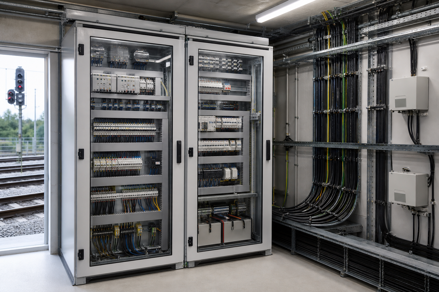
A specification checklist for railway signal power
Class: PC-class with upstream short-circuit protection is the safe default for relatively reliable railway feeds; verify CB-class breaker selection and coordination if used.
Poles: three-pole for same-family supplies with shared neutral; four-pole when configurations, capacity or harmonics differ.
Positions: two-position for fast transfer on first-class loads; three-position only when inrush mitigation demands the zero stop.
Isolation: always add an upstream isolating device; the transfer unit itself is not an isolator.
Time: transfer time must exceed arcing time and coordinate per the 200 ms and 0.5 s rules with adjacent and tie-breaker levels.
This guide supports initial technical discussion only. Final ratings, standards, protection coordination, drawings and configuration must be confirmed for the actual project requirement.
Frequently asked questions
Why do railway signal systems need dual-power transfer?
Signalling is a first-class load in Chinese railway design: two supplies are run to a dual-power changeover box so that a feed failure does not interrupt train operations.
What are the four transfer architectures used in Chinese railway projects?
Two-contactor, two-breaker (CB-class), excited transfer switch, and motor-driven load-break switch (PC-class). The contactor type is largely obsolete; the others remain in service.
PC-class or CB-class — which fits railway signal loads?
Because the two 10 kV railway feeds are relatively reliable, PC-class transfer with upstream short-circuit protection is usually safer; CB-class adds protection levels and can fail to transfer when its breaker trips on overcurrent while the feed itself is healthy.
When should a three-pole or four-pole transfer switch be used?
Three-pole for identical supplies sharing a neutral (two grids, two generator sets). Four-pole when the supplies differ in configuration or capacity or carry significant harmonics, to avoid neutral circulating currents.
How is transfer time determined and coordinated?
Transfer time is switching time plus any deliberate delay and must exceed the arcing time; downstream units must act more than 200 ms after upstream ones, and about 0.5 s after a tie-breaker interlock transfer.
Discuss Your Transfer-Switch Requirement
Share the supply arrangement, load duty, operating environment and document requirement so the relevant configuration can be reviewed before quotation.
Discuss a projectContinue learning
Explore related technical guidance in Power Distribution.
Technical note: this article is published from the approved 2026-08-24 source package. Confirm the final electrical design, local code basis and manufacturer documentation for the actual project.