

Why maintenance discipline matters
The ATS is the single point where the load moves from the preferred supply to the standby supply. Because it operates rarely, small problems — a loose sampling wire, a wrong DIP-switch position, a fatigued fuse — can hide for months and surface exactly during a changeover. Scheduled inspection, correct wiring discipline and documented settings are the cheapest insurance for a device that has no second chance in an emergency.
First response: reset and inspect
When a transfer switch misbehaves, the first response should always be the same: press the reset button and see whether the fault clears, then inspect the incoming and standby feeds, the voltage sampling wires and all plug-in connectors for looseness or poor contact. A large share of reported failures resolves at this stage without any part replacement.
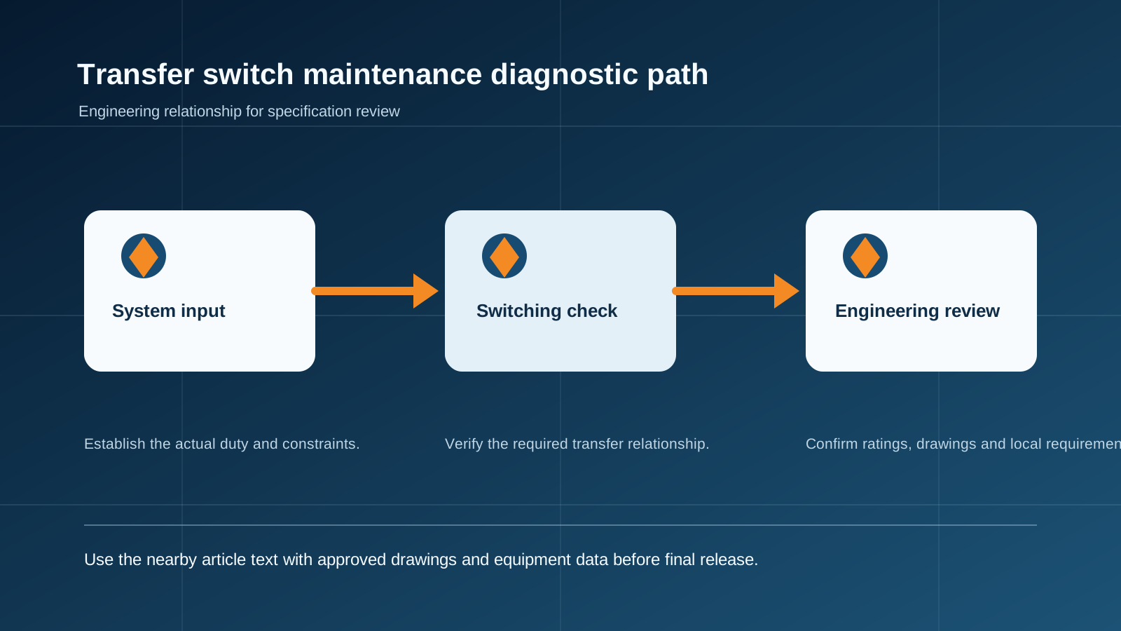
Technical diagram shown at a readable responsive scale.
Fault 1: unit does not operate, controller LED off
Symptoms: the ATS does not act when power is applied and the controller power LED is dark. Likely causes: incorrect or loose installation wiring, or a blown fuse link in the fuse holder.
Fix steps:
Check the breaker incoming terminals for loose or detached conductors and re-terminate firmly.
On a 3-pole ATS, verify the neutral conductor is connected to the neutral terminal — a floating neutral is a classic no-operation cause.
Replace a blown fuse link, then re-test the controller power circuit.
Fault 2: unit does not operate, controller LED on
Symptoms: the controller is powered (LED on) but the transfer switch does not act. Likely causes: the unit is not in automatic mode, or the transfer delay has been set too long.
Fix steps:
Confirm the auto/manual selector is in the automatic position and that the controller auto-transfer indication is active.
If the unit is set to "automatic transfer without return" or to mutual-standby mode, it will not return the load to the preferred feed; reconfigure the DIP switches and controller to auto-return as required by the application.
If the transfer delay has been adjusted too long, restore the delay DIP-switch and controller setting.
Fault 3: controller power LED flashing
Symptoms: the power LED flashes, often with a buzzer alarm. Likely causes: an incoming supply fault such as overvoltage, poor supply contact, phase loss, reversed neutral/phase wiring, or a controller fault.
Fix steps:
Re-adjust the incoming supply voltage to the correct band.
Check both feeds for phase loss and loose connections — including the voltage sampling wires — and re-terminate.
Re-seat the controller plug-in connector or replace the controller if the fault persists.
Verify neutral and phase wiring polarity on the incoming terminals and correct any reversal.
Fault 4: trip indicator lit
Symptoms: the trip indicator is lit, meaning the moulded-case breaker inside the ATS has tripped. Causes fall into two groups: a trip caused by transport (the unit was shipped with the breaker tripped) or a trip during service.
Fix steps:
Transport trip: manually re-latch the breaker, then press the reset key and return the unit to automatic mode.
Service trip — short circuit: first clear the short-circuit condition, and only then attempt manual or automatic transfer. Transferring into an uncleared fault can cause a second short circuit and risk personal injury.
Service trip — overload: check the connected load and verify that the breaker rating inside the ATS still covers the duty. If not, replace the breaker with a correctly rated unit; otherwise repeated tripping will burn the moving and fixed contacts and degrade the supply.
Fault 5: controller OK but no transfer
Symptoms: controller operation appears normal but the ATS does not transfer. Likely causes: a faulty panel indicator wiring loop, a loose controller plug, or a damaged controller.
Fix steps:
Unplug the panel indicator connector and test the ATS live: if transfer now works, re-terminate the indicator wiring correctly.
Pull and re-seat the controller plug connector firmly, then re-test.
If the controller was damaged by site overvoltage or another cause, replace it with the same specification unit.

A preventive maintenance checklist
Monthly: press reset and exercise one manual transfer to confirm mechanical freedom of the mechanism.
Quarterly: check incoming/standby terminal torque and all sampling-wire connectors; verify neutral polarity on 3-pole units.
Annually: verify DIP-switch and controller settings against the design (auto-return, delay, mode).
After any short-circuit event: inspect the breaker contacts for burn or welding before returning to service.
Document every fault and fix; recurring patterns point to a rating or configuration problem, not bad luck.
This guide supports initial technical discussion only. Final ratings, standards, protection coordination, drawings and configuration must be confirmed for the actual project requirement.
Frequently asked questions
What should I check first when an ATS fails?
Press the reset button, then inspect the feeds, the voltage sampling wires and all plug-in connectors for looseness. Most reported failures resolve at this stage.
Why is the ATS not switching when the controller LED is on?
The unit may be left in manual mode, set to auto-transfer-without-return, or the transfer delay may be set too long. Check the auto/manual selector, the DIP switches and the controller settings.
What does a flashing controller power LED mean?
It usually signals an incoming supply problem — overvoltage, phase loss, loose contact, or reversed neutral/phase wiring — or a controller fault. Check the feed, the sampling wires and the controller plug.
What should I do after a short-circuit trip?
Clear the short-circuit condition first, then re-latch and transfer. Never transfer into an uncleared fault; inspect the breaker contacts for burn or welding before returning to service.
When should the ATS circuit breaker be replaced?
When it trips repeatedly on overload because its rating no longer covers the load. Replace it with a correctly rated unit; repeated tripping burns the contacts and degrades the supply.
Discuss Your Transfer-Switch Requirement
Share the supply arrangement, load duty, operating environment and document requirement so the relevant configuration can be reviewed before quotation.
Discuss a projectContinue learning
Explore related technical guidance in Power Distribution.

Technical note: this article is published from the approved 2026-08-24 source package. Confirm the final electrical design, local code basis and manufacturer documentation for the actual project.