
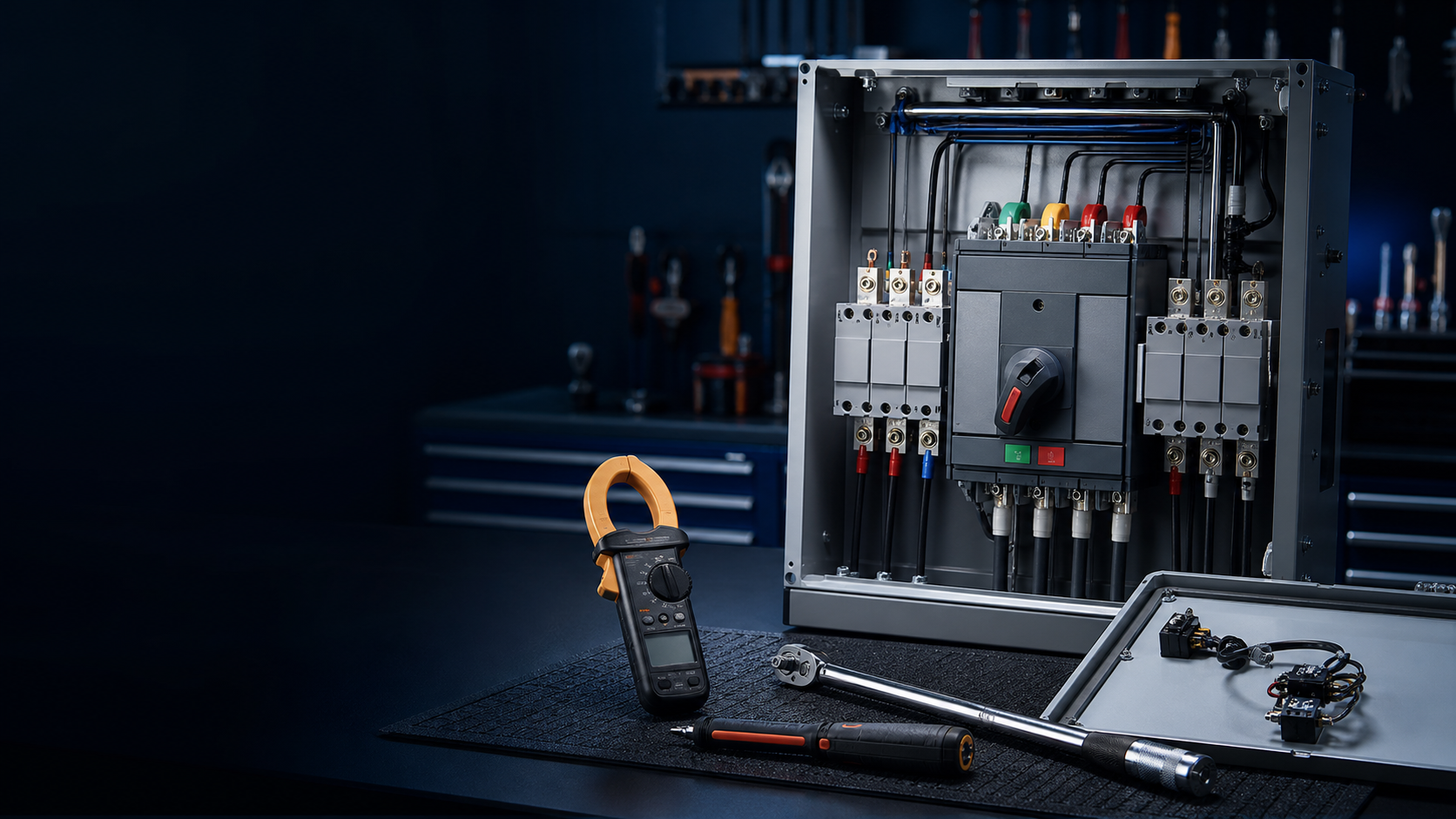
How the ATS works and what can fail
An ATS monitors both supplies with its intelligent controller and drives the actuator to transfer the load between the preferred and standby feeds. The core components are the logic control unit, the mechanical transmission, the power contact module and the protection system. Typical designs use a double-break contact arrangement for physical isolation, an arc-extinguishing device to suppress switching arcing, and an integrated overload protection module. Each of these has its own characteristic failure mode, which is why diagnosis should start from the symptom and follow a fixed measurement sequence.
Diagnosing contact-system failure
The first failure pattern is loss of switching function caused by the contact system. Diagnose it with an insulation-resistance tester to measure the contact resistance of the power contacts: the healthy value should be below 50 mΩ. When the reading is high, inspect for welding or oxidation; in either case the contactor group must be replaced as a complete assembly rather than patched, because mixed old and new contacts have different pressure and surface states.
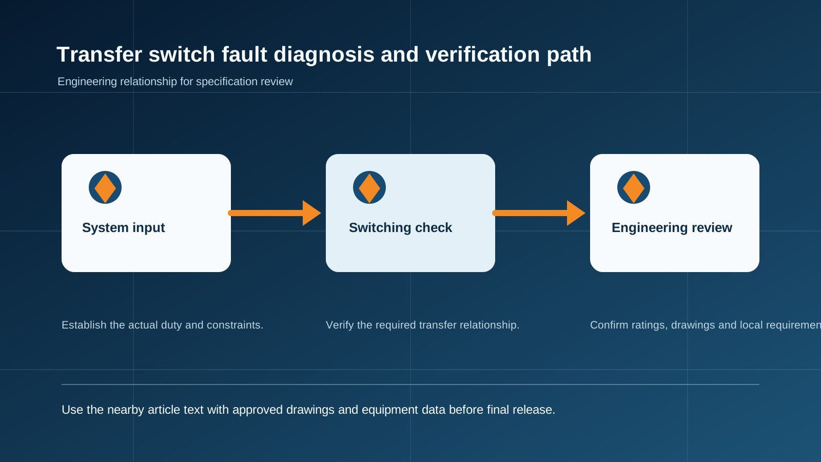
Technical diagram shown at a readable responsive scale.
Diagnosing false protection trips
When the protection seems to operate without a real fault, work through the causes in a fixed order: first confirm whether the load current actually exceeds the rating — use a clamp meter on the output; then check the state of the short-circuit protective device; and finally verify the sampling accuracy of the voltage monitoring module. This sequence eliminates the load as the cause before blaming the protection chain.
Diagnosing abnormal heating
Heating that is not explained by load should be investigated in three places: the tightening torque of the main-circuit connection terminals (per the manufacturer’s specification), the spring force of the contact-pressure springs, and the clearness of the cooling-air path. A loose terminal or a fatigued spring raises resistance at the joint, and the resulting heat accelerates oxidation — a loop that only ends with contact failure.
Standard repair procedures
Repairs should follow written standards so that every unit is restored to the same quality:
Contactor replacement: disconnect all power before work; measure the coil resistance of the new contactor (tolerance within ±5% of the rating); after installation run 20 no-load transfer cycles to prove the mechanism.
Protection calibration: set overcurrent protection at 1.25 times the rated current, and set the transfer delay in the 1–3 second range; verify with a professional relay test set rather than by judgement.
Documentation: record the measured values and settings so the next inspection can compare against the baseline.
Scheduled mechanical maintenance
The mechanical transmission needs periodic attention even when no fault appears: check the lubrication of the transmission and clear accumulated dust every quarter; measure the operating torque once a year, and replace the reduction gear set when the torque exceeds the standard value by 15%. Catching a rising torque early prevents a seized mechanism at the exact moment of an emergency transfer.
Safety and verification after repair
Work on an ATS is live-side work: wear insulated gloves, and set up warning signs before opening the unit. After any repair, run three simulated power-failure transfer tests and confirm that every indicator matches the actual operating state — the unit is only back in service when the panel says what the mechanism did.
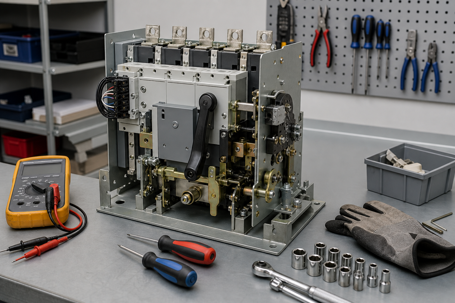
A repair-readiness checklist
Instruments on hand: insulation-resistance tester, clamp meter, torque wrench, relay test set.
Thresholds posted: contact resistance <50 mΩ; coil tolerance ±5%; overcurrent 1.25x rated; transfer delay 1–3 s; torque action at +15%.
Procedure locked: power off, diagnose by sequence, replace as an assembly, 20 no-load cycles, three simulated transfer tests.
Records kept: baseline values and settings documented for trend comparison.
Spares policy: keep matched contactor assemblies and reduction gear sets available to avoid long outages.
This guide supports initial technical discussion only. Final ratings, standards, protection coordination, drawings and configuration must be confirmed for the actual project requirement.
Frequently asked questions
How do I measure contact wear on a transfer switch?
Use an insulation-resistance tester to measure the power-contact resistance; a healthy contact reads below 50 mOhm. Higher readings point to oxidation or welding, and the contactor group should be replaced as an assembly.
What is the normal contact resistance for an ATS?
Below 50 mOhm measured across the power contacts. Values above this usually indicate oxidation, loose pressure or welding.
How should overcurrent protection be calibrated?
Set the overcurrent protection at 1.25 times the rated current and the transfer delay in the 1-3 second range, then verify with a professional relay test set.
How often should the transfer mechanism be maintained?
Lubricate and clean the transmission quarterly; measure the operating torque annually and replace the reduction gear set when it exceeds the standard value by 15%.
What verification is required after a repair?
Run three simulated power-failure transfer tests and confirm that all indicators match the actual operating state before returning the unit to service.
Discuss Your Transfer-Switch Requirement
Share the supply arrangement, load duty, operating environment and document requirement so the relevant configuration can be reviewed before quotation.
Discuss a projectContinue learning
Explore related technical guidance in Power Distribution.

Technical note: this article is published from the approved 2026-08-24 source package. Confirm the final electrical design, local code basis and manufacturer documentation for the actual project.