 NEUTRONPower Distribution & New Energy
Menu
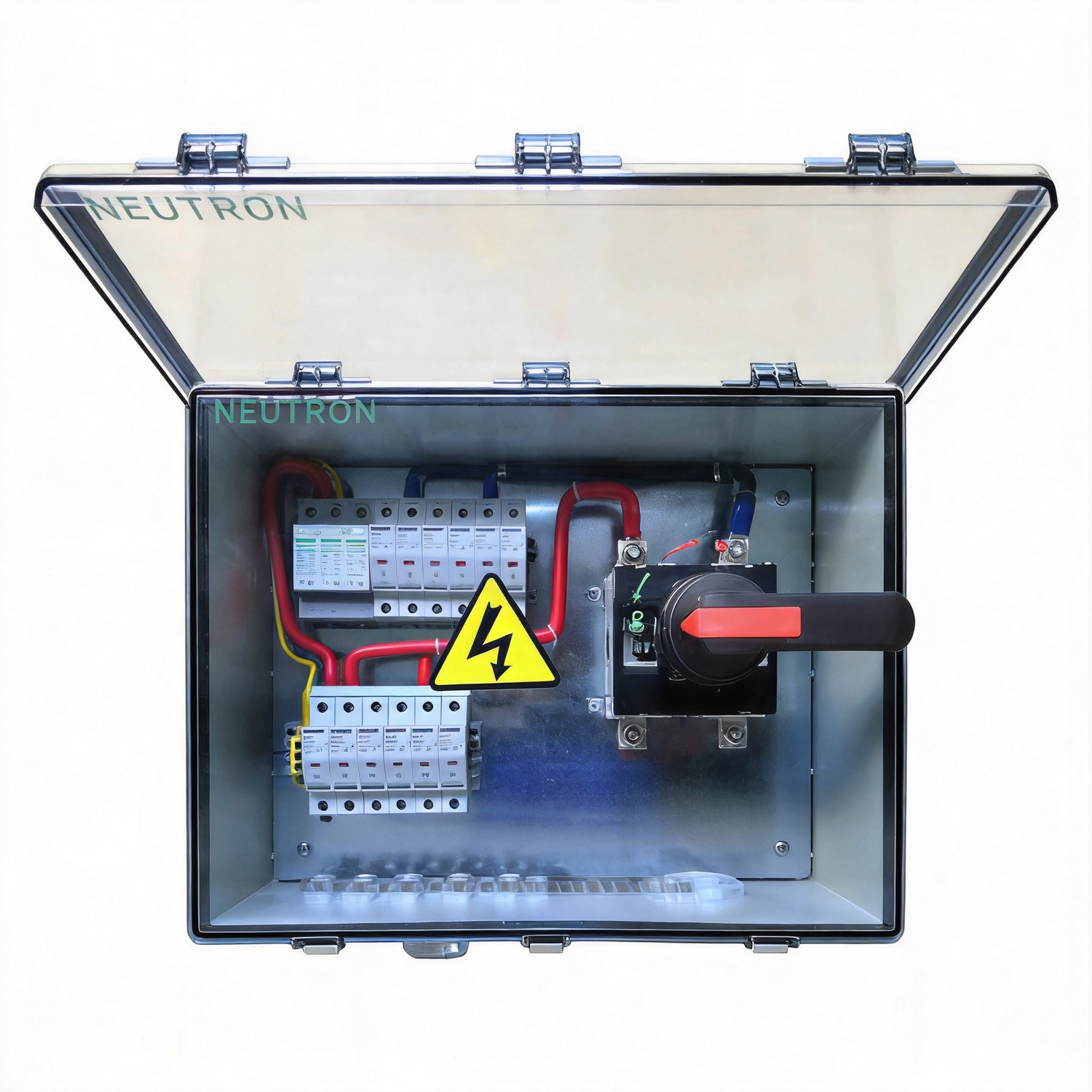
PV combiner configuration family
High-String DC Disconnect Combiners
High-string 1000V/1500V DC disconnect configurations for PV collection systems. This family groups 6 reviewed configurations by voltage, input/output topology and protection architecture.
Purchase readiness
Move from product interest to a review-ready request.
Pricing is confirmed per configuration and quotation. Project builds are engineered to spec; final ratings, documents and delivery are confirmed before quotation.
- MOQ
- 1 unit
- FOB
- Ningbo / Shanghai
- Standard lead time
- 3-5 days
- Project lead time
- 5-30 days
- Sample route
- 3-5 days
Configuration matrix
Compare the electrical boundary before selecting a model.
Values shown are source-backed configuration identifiers. Final component selections, ratings, drawings and documents are confirmed against the project specification.
DC disconnect combiner
- Voltage
- 1000V DC
- Input / output
- 6 / 1
- Arrangement
- load-break disconnect
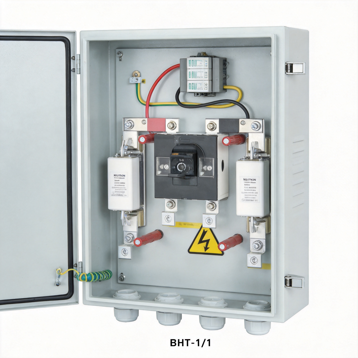
DC disconnect combiner
- Voltage
- 1500V DC
- Input / output
- 1 / 1
- Arrangement
- load-break disconnect
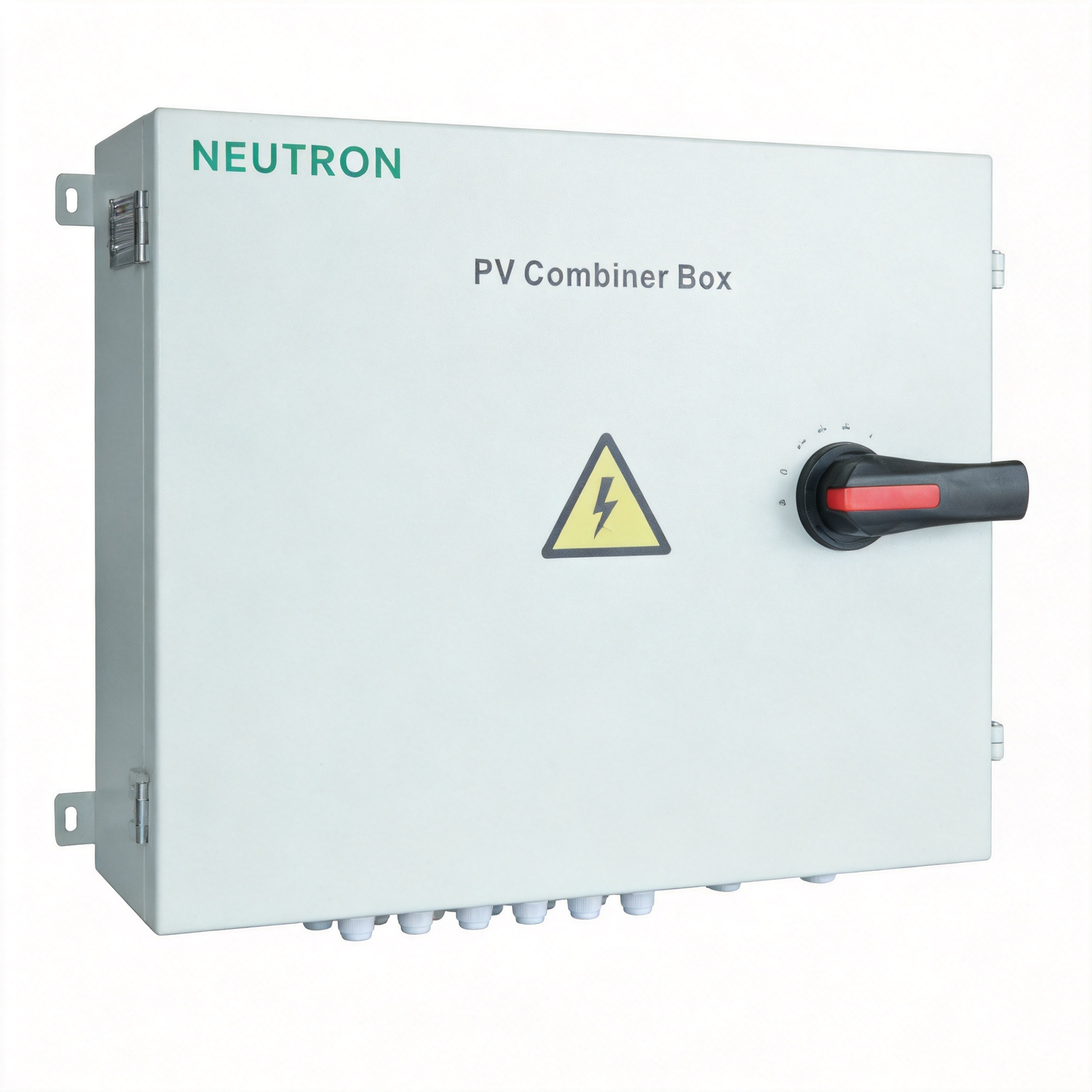
DC disconnect combiner
- Voltage
- 1000V DC
- Input / output
- 12 / 1
- Arrangement
- disconnect + SPD
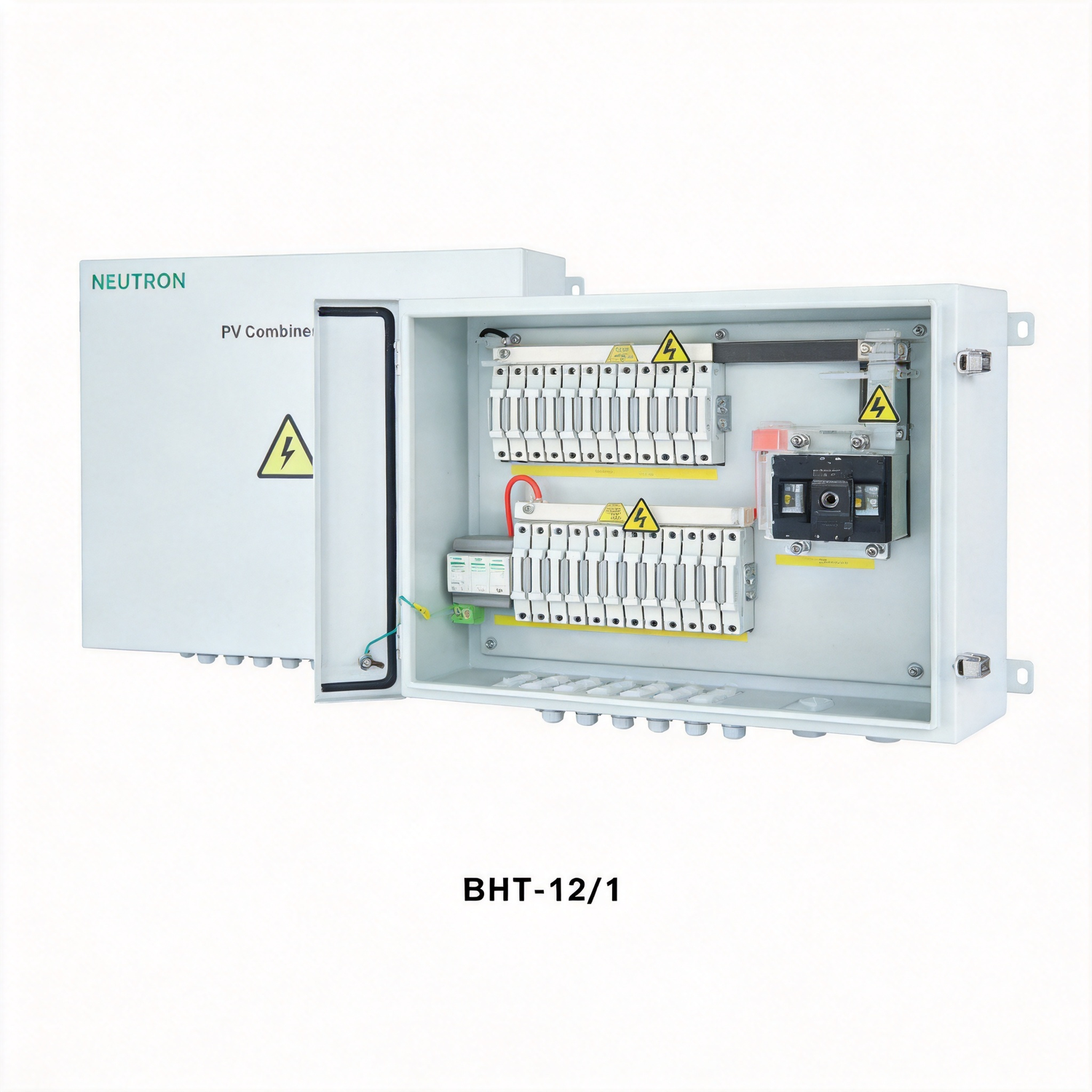
DC disconnect combiner
- Voltage
- 1500V DC
- Input / output
- 12 / 1
- Arrangement
- disconnect + SPD
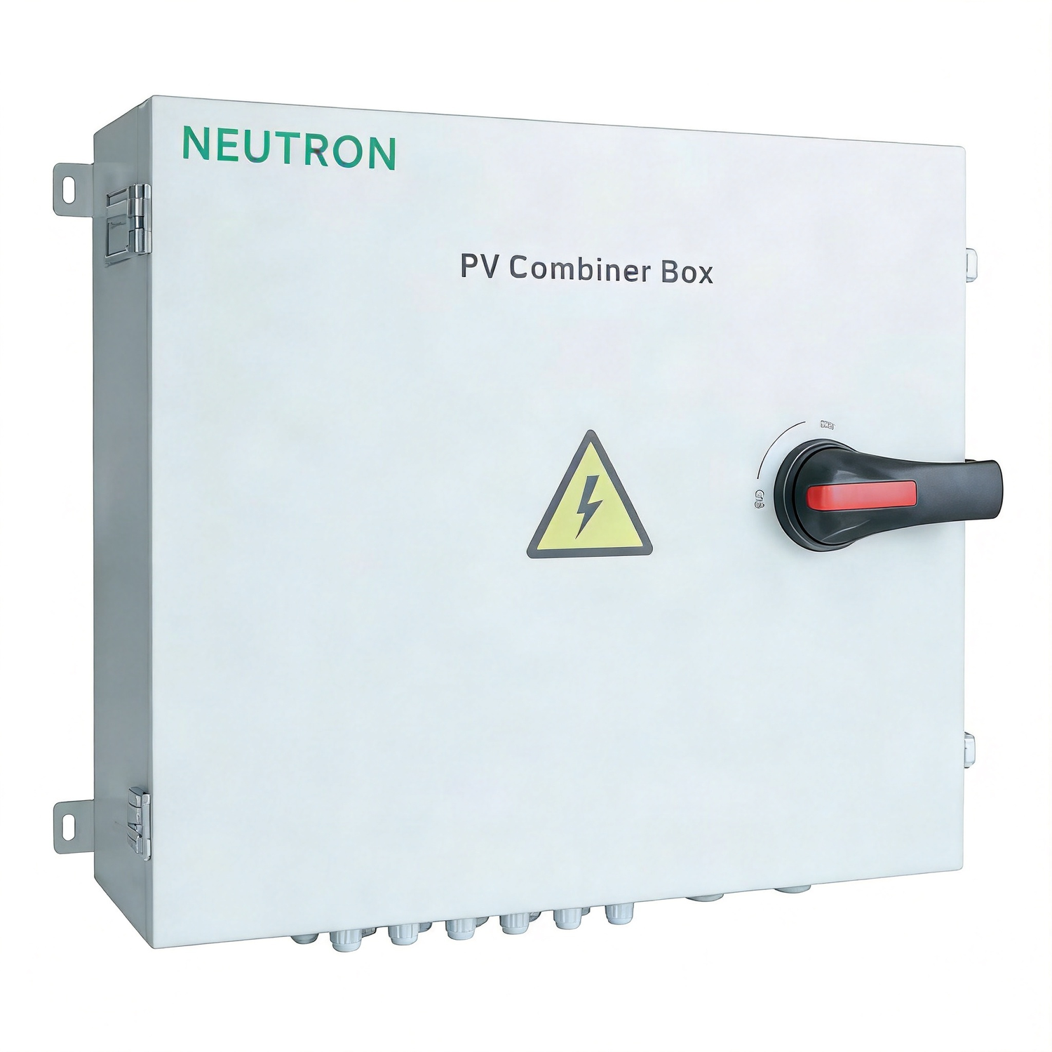
DC disconnect combiner
- Voltage
- 1000V DC
- Input / output
- 16 / 1
- Arrangement
- disconnect + SPD
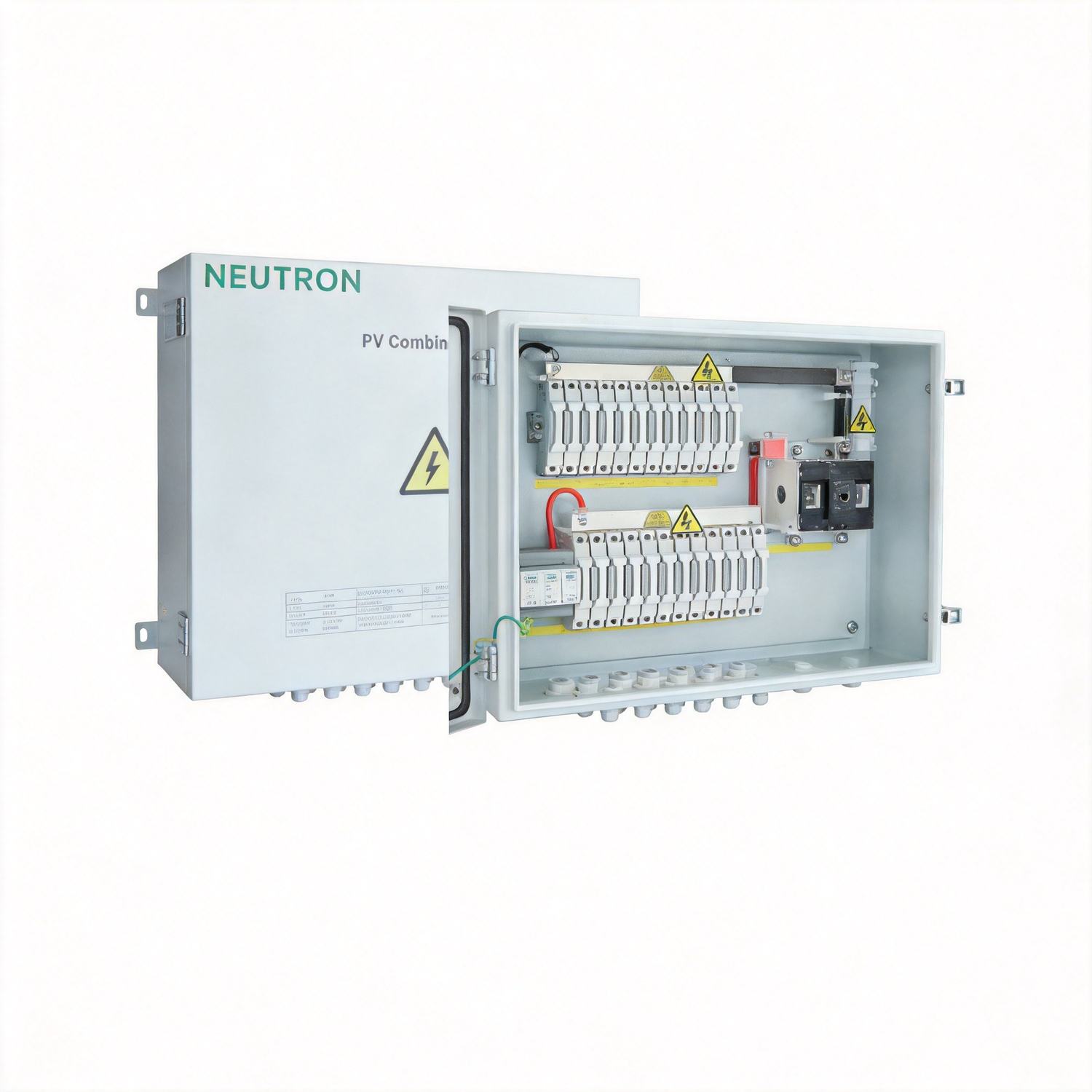
DC disconnect combiner
- Voltage
- 1500V DC
- Input / output
- 16 / 1
- Arrangement
- disconnect + SPD
Technical reading
Continue with the engineering question behind the configuration.
Why 1500 V Is the Utility PV Standard for DC Protection
The move to 1500 V is a response to project economics at the megawatt scale. A 1500 V array carries roughly the same power with two-thirds of the current of an equivalent 1000 V design, which shrinks conductor cross-sections, lowers resistive losses, and reduces the number of combiner boxes and inverters needed per hectare. As module currents and conversion efficiencies climb, the industry has pushed the standardized maximum system voltage upward to keep the levelized cost of energy falling. For equipment engineers, the change is not cosmetic: every component on the DC side must now be qualified for the higher insulation and transient environment.
Read Insight →Solar PV / Technical guide1500V DC Solar BOS Selection: Cable, Connector and Junction Box
The move from 1000V to 1500V maximum DC system voltage, enabled by NEC 690.7 amendments and IEC 60364-7-712 revisions, changed the economics of solar balance of system (BOS). A 1500V system fits roughly 1.5x more modules per string before hitting the inverter MPPT voltage ceiling, which means fewer strings per inverter.
Read Insight →Solar PV / Technical guidePV String Protection Basics: gPV Fuses & Monitoring
Where PV strings are paralleled, healthy strings can backfeed a faulted string, so the prospective fault current is not limited to a single module. The protection task is to clear that fault fast while never interrupting normal operation. Three realities drive the design:
Read Insight →Solar PV / Application guideUtility-Scale PV Grid Connection: Equipment Coordination
A large PV plant is assembled as a sequence of conversion and collection stages. At the array, strings feed combiner boxes that consolidate DC current. From there, collector lines carry that energy to a central step-up substation, where transformers raise the voltage and switchgear connects the plant to the grid. Ring main units (RMUs) and other switchgear manage how feeders are switched and protected along the way. Each stage has its own voltage level, protection philosophy and equipment envelope, and the whole chain must be specified as one system rather than as independent purchases.
Read Insight →