
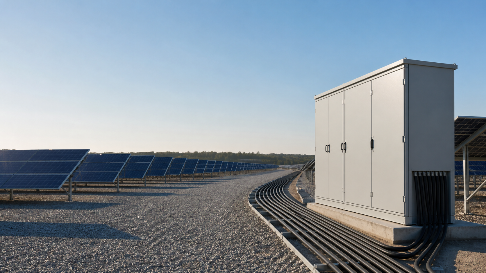
Why 1500V became the utility standard
The move from 1000V to 1500V maximum DC system voltage, enabled by NEC 690.7 amendments and IEC 60364-7-712 revisions, changed the economics of solar balance of system (BOS). A 1500V system fits roughly 1.5x more modules per string before hitting the inverter MPPT voltage ceiling, which means fewer strings per inverter.
- Fewer strings means fewer combiner box inputs, fewer disconnects and shorter home-run cable runs.
- DC BOS material and installation cost typically falls 10-20% for utility-scale projects.
- The premium for 1500V-rated BOS hardware over 1000V is normally 0-3%, making the higher class the economic default.
Cable: H1Z2Z2-K (EN 50618 / IEC 62930)
H1Z2Z2-K is the current IEC designation for cross-linked polyolefin (XLPE) insulated, halogen-free outer sheath solar cable. It supersedes PV1-F and is the standard cable for TUV-certified 1500V DC installations. The 2Z2 suffix marks the XLPE insulation and halogen-free sheath combination, relevant for fire safety in enclosed rooftop and carport spaces.
Cable sizing follows four steps: calculate the maximum continuous DC current (typically 1.25 x Isc at STC to cover irradiance above STC), apply derating factors for installation temperature and bundling, verify voltage drop, then select the smallest cross-section that satisfies both current and voltage drop criteria.
Voltage drop math with a worked example
For a single cable run carrying both conductors, voltage drop is calculated as: dV = (2 x L x I x rho) / A, where L is one-way length in metres, I is DC current in amperes, rho is conductor resistivity (0.0175 ohm.mm2/m at 20C, 0.0215 at 90C operating temperature) and A is cross-section in mm2. IEC 62548 recommends keeping string cable voltage drop within 1% of system voltage.
Worked example: a 1500V system with a 15A string and a 60m one-way run on 4mm2 cable gives dV = (2 x 60 x 15 x 0.0215) / 4 = 9.7V, equal to 0.65% of 1500V. The run is inside the 1% limit, so 4mm2 is correct. Using the 20C resistivity of 0.0175 instead gives 7.9V, 0.53%.
Connectors: MC4 ratings and the no-mixing rule
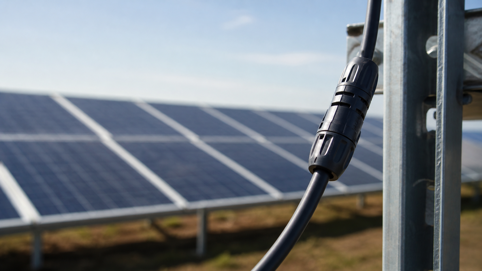
MC4 connectors are the universal DC string interconnect. IEC 62852 defines the 1500V test requirements: contact resistance at or below 0.5 milliohm before and after environmental conditioning, IP68 at 1m depth for 24 hours, UV resistance to 3000 kJ/m2, and mechanical pull-out force of at least 80N for the 4mm version.
Mixing connector brands is prohibited by every major manufacturer. Pin diameter, contact spring force and seal geometry differ between brands by 0.1-0.3mm, enough to reduce contact force and create resistance hotspots at operating current. Fire investigation reports on PV systems repeatedly cite mixed-brand mating as a contributing factor. Specify one connector brand for the whole project and do not substitute on partial shipments.
Junction box and bypass diode selection
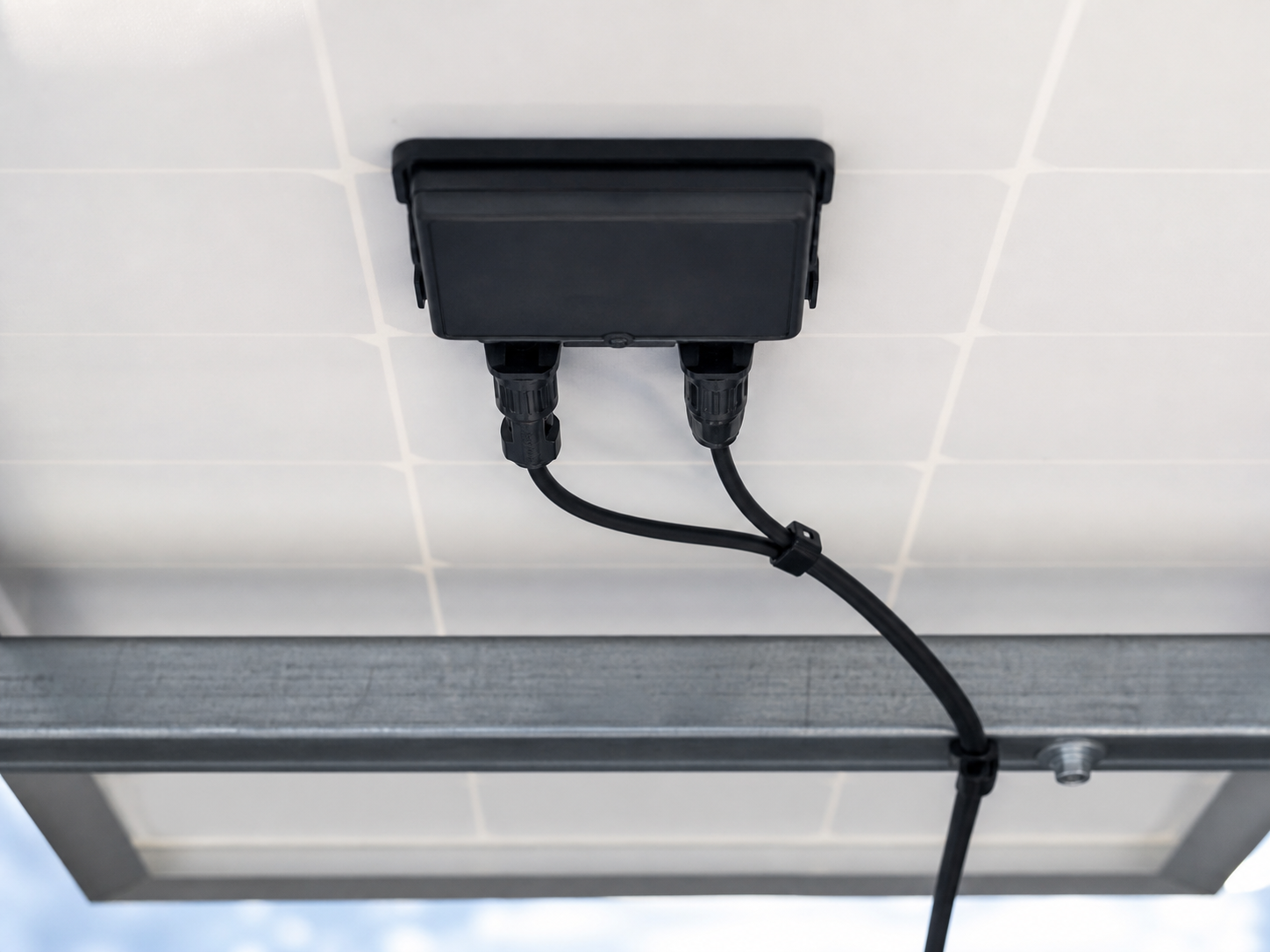
The PV junction box terminates the cell string connections and houses the bypass diodes. IEC 62790 covers the test requirements: IP68, thermal cycling from -40C to +90C, UL94-5VA flame class for building-applied systems, and cable gland pull-out force.
- Bypass diode current rating must exceed module short-circuit current: 15A Schottky diodes suit modules with Isc up to 12A.
- High-current bifacial HJT and TOPCon modules with Isc above 15A need 20A or 30A rated diodes; confirm against the module datasheet.
- Half-cut modules should align the junction box cable entry with the cell string division, typically one third from each end.
How BOS ratings flow into combiner boxes and DC protection
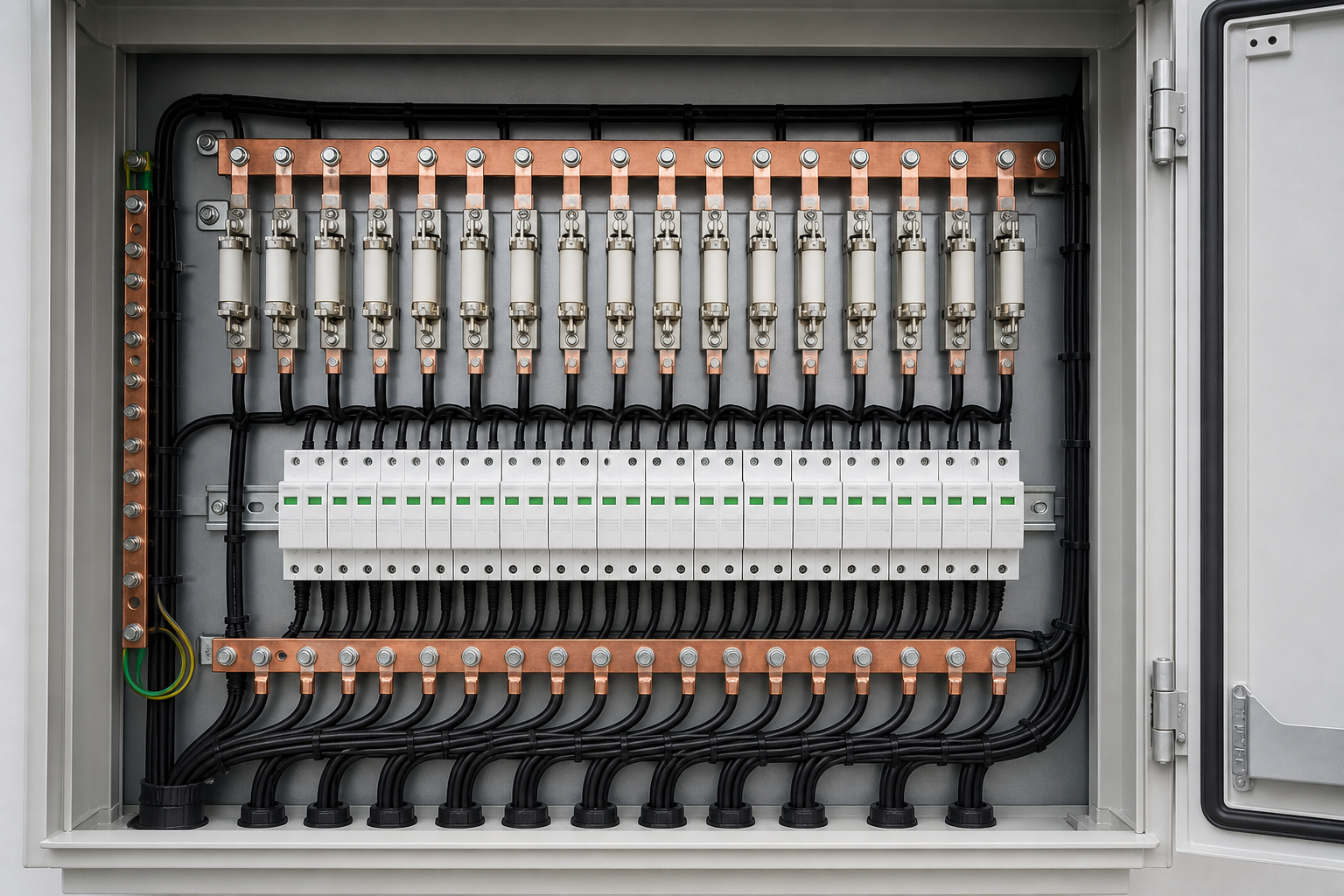
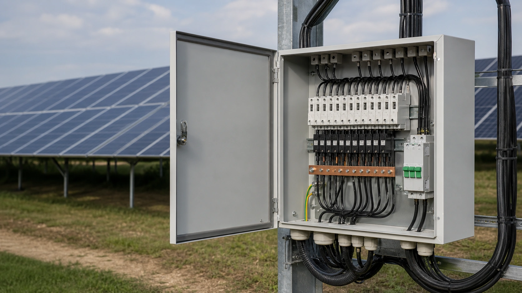
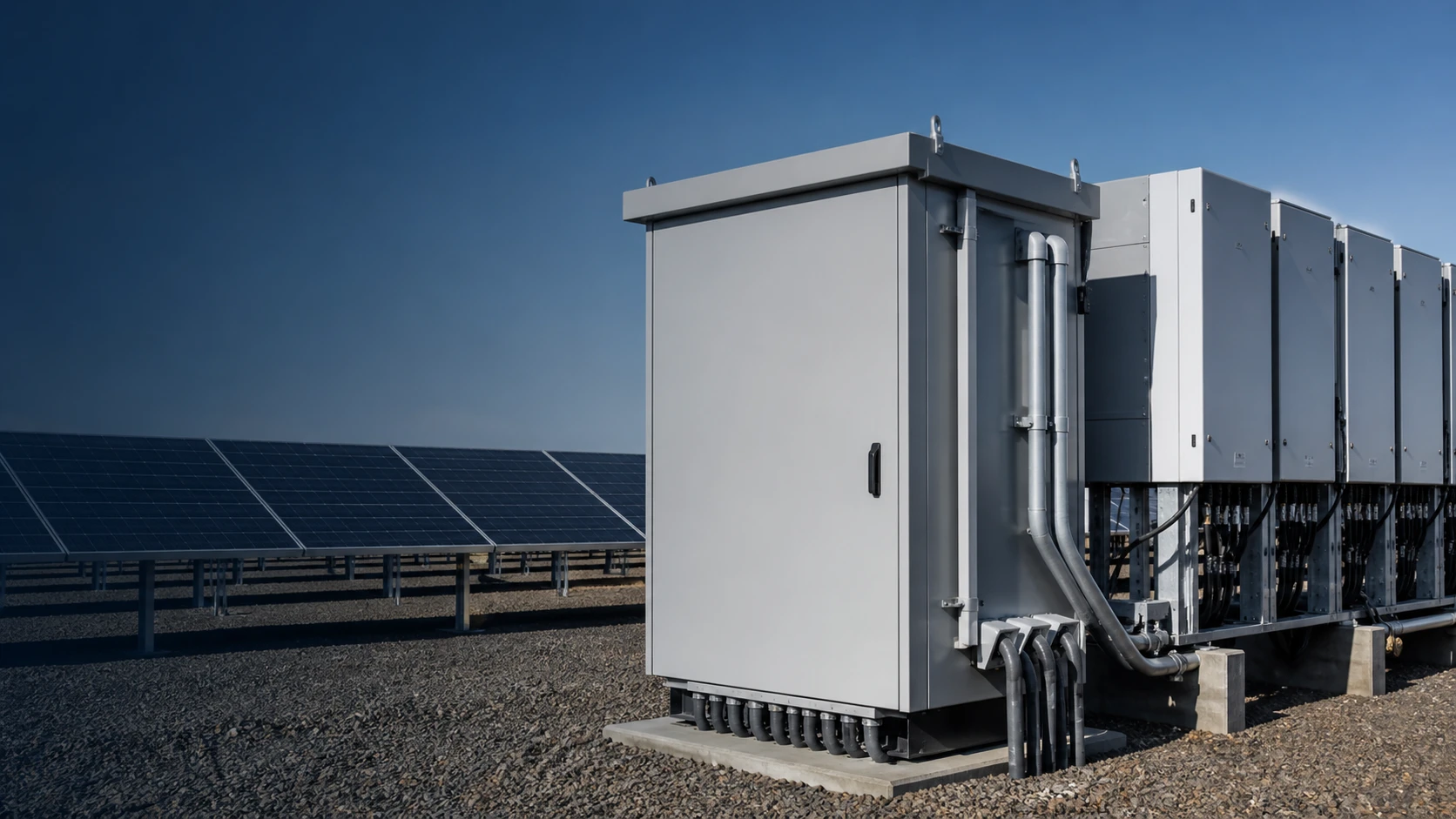
The 1500V class applies end to end. A combiner box collecting 1500V strings must carry a DC isolation switch rated for 1500V, an SPD whose voltage protection level and maximum continuous operating voltage match the insulated bus, and clearance and creepage distances sized for the maximum system voltage plus transient margin.
Each string still needs its own gPV fuse sized at 1.25 x Isc, and the output busbar must aggregate the sum of protected strings. NEUTRON sizes combiner boxes and the DC protection layer from the actual module and string data of each project.
Standards quick reference
- EN 50618 / IEC 62930 - solar cable (H1Z2Z2-K).
- IEC 62852 - connectors for DC applications in PV systems.
- IEC 62790 - junction boxes for PV modules.
- IEC 60364-7-712 - PV supply installations.
- IEC 60269-6 - gPV fuses for photovoltaic protection.
What to specify at RFQ
When you issue a 1500V BOS enquiry, five numbers decide the quotation: maximum system DC voltage, string short-circuit current, one-way cable run, connector brand, and bypass diode class. Hand these to the supplier and the BOS package you receive will match the array you are installing.
This guide supports an initial technical or commercial review. Final ratings, standards, shipping terms, documentation and configuration must be confirmed for the actual project requirement.
Frequently asked questions
Can I mix MC4 connectors from different manufacturers?
No. IEC 62852 qualifies connectors against their own mating counterpart, not against other brands. Pin diameter, contact spring force and seal geometry differ between brands, creating resistance hotspots. Use one brand throughout a string and across the project.
What cable cross-section is needed for a 1500V 15A string?
A 4mm2 H1Z2Z2-K cable rated 32A at 60C installation is the standard selection. For a 50m one-way run at 15A, voltage drop is about 6.6V or 0.44% of 1500V, inside the 1% guideline. Longer runs above 100m or currents above 20A need a full IEC 60364-7-712 calculation.
What is the difference between H1Z2Z2-K and PV1-F cable?
H1Z2Z2-K (EN 50618 / IEC 62930) uses XLPE insulation with a halogen-free outer sheath and is rated for 90C conductor temperature. PV1-F is the older HD 605 designation with a PVC outer sheath and a 70C rating. H1Z2Z2-K has replaced PV1-F in current certified production.
How many bypass diodes does a PV junction box need?
Standard 60-cell and 72-cell modules use three bypass diodes, one per substring. Half-cut modules (120-cell and 144-cell) also use three in standard configurations, each protecting 40 or 48 half-cells. High-current modules above 15A Isc require 20A or 30A rated diodes.
Why did the industry shift from 1000V to 1500V DC?
The higher voltage allows roughly 50% more modules per string. Longer strings reduce the number of strings per inverter, the number of combiner inputs and the DC cable quantity, cutting DC BOS cost by 10-20% for a 1MW project and improving efficiency through lower I2R losses.
Bring the project inputs together
Use the checklist and technical inputs in this guide to prepare a clear project discussion.
Discuss a projectContinue learning
Explore related technical guidance in Solar PV.
Technical note: final ratings, standards, shipping terms, documentation and configuration remain subject to the agreed project requirement.