
1. The shift from 1000 V to 1500 V in utility PV
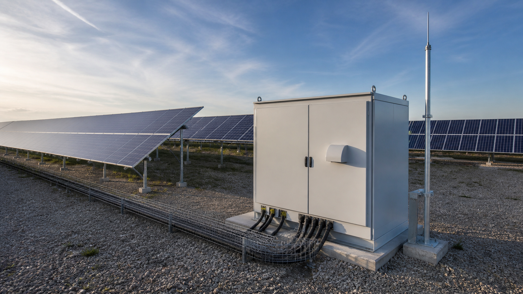
The move to 1500 V is a response to project economics at the megawatt scale. A 1500 V array carries roughly the same power with two-thirds of the current of an equivalent 1000 V design, which shrinks conductor cross-sections, lowers resistive losses, and reduces the number of combiner boxes and inverters needed per hectare. As module currents and conversion efficiencies climb, the industry has pushed the standardized maximum system voltage upward to keep the levelized cost of energy falling. For equipment engineers, the change is not cosmetic: every component on the DC side must now be qualified for the higher insulation and transient environment.
2. Why 1500 V lowers BOS cost and losses
Balance-of-system savings come from three physical facts:
These gains are why the 1500 V architecture has become the default for new utility installations. The trade-off is that all DC-side protection must be re-rated for the new voltage class rather than carried over from a 1000 V design.
- Lower current for the same power means thinner string and feeder conductors — a direct material saving at utility scale.
- Reduced I²R losses improve the energy yield of the array, because less power is dissipated as heat in wiring.
- Fewer combiner boxes, DC disconnects and inverter units are needed to collect the same plant capacity, cutting labor and enclosure count.
Technical diagram shown at a readable responsive scale.
3. DC protection requirements at 1500 V
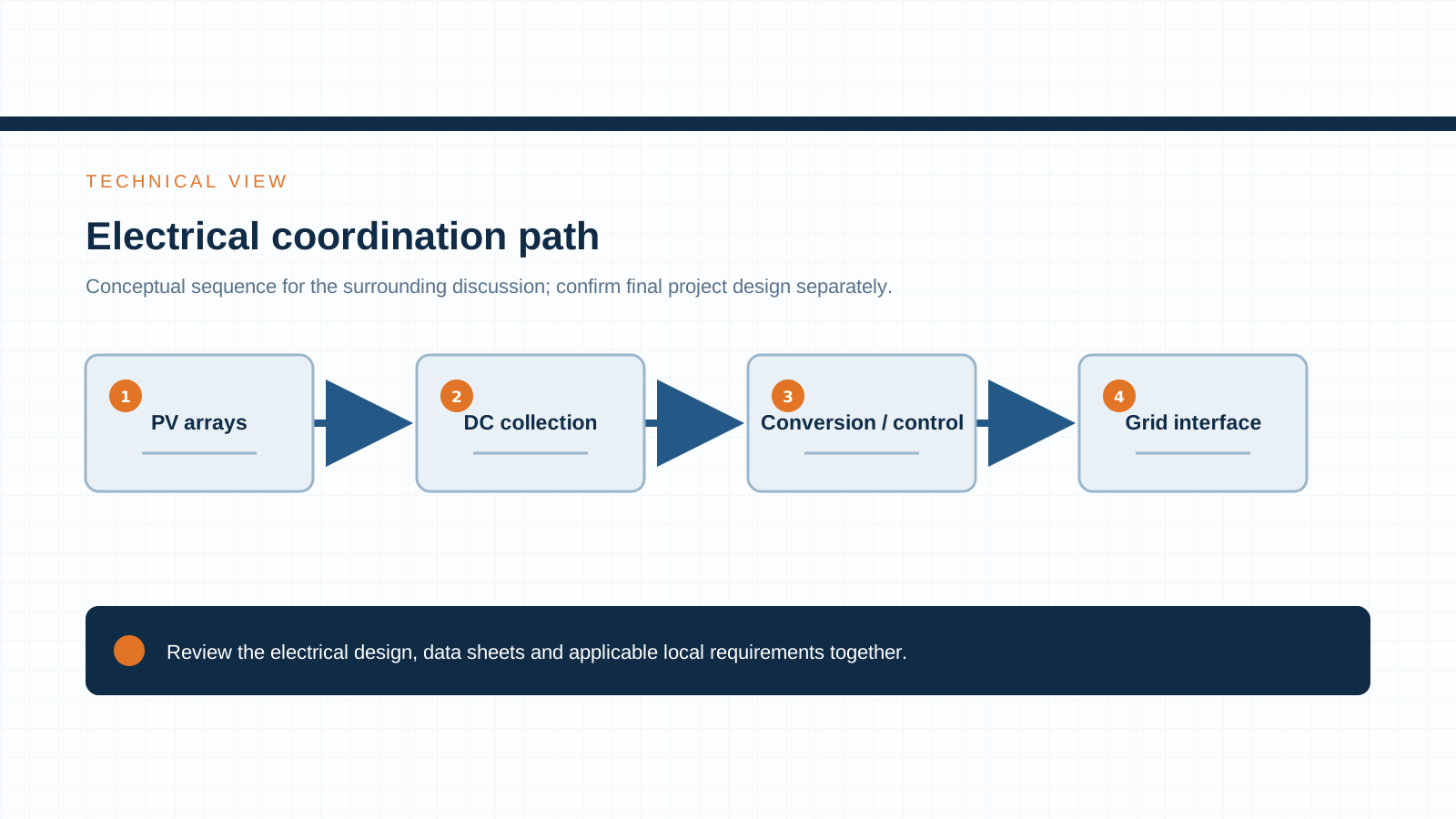
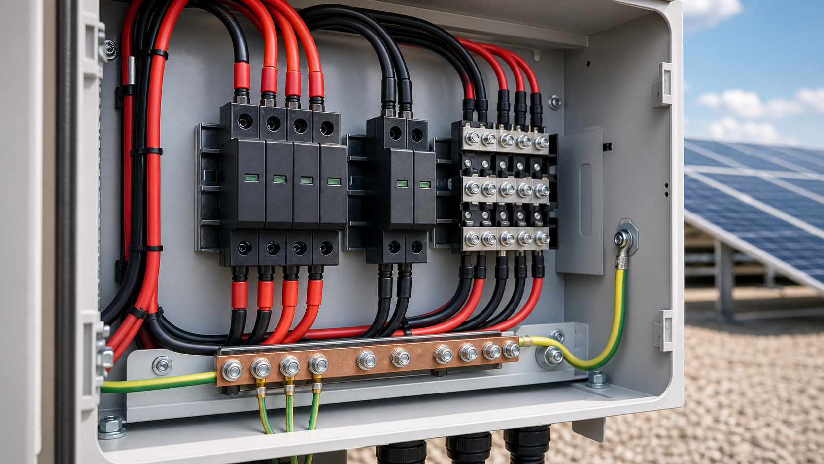
Every string entering a combiner box must be isolated, overcurrent-protected and surge-protected for the 1500 V envelope. The protection chain has four stations:
Each station is independent but coordinated. A weak link — an SPD selected for a 1000 V class, for example — undermines the whole chain even if the fuse and disconnect are correct.
- A gPV fuse on each string input sized to the string short-circuit current.
- A DC disconnect switch rated for 1500 V with adequate breaking capacity.
- A surge protective device (SPD) matched to the 1500 V maximum continuous operating voltage.
- Insulation, clearance and creepage inside the enclosure sized for the higher system voltage plus transient margin.
4. gPV fuse and DC disconnect rating at 1500 V
The gPV fuse remains the primary overcurrent protective device for each PV string. Per IEC 60269-6, the fuse is sized to no less than 1.25 × the string short-circuit current (Isc) to accommodate real operating peaks. At 1500 V the fuse must additionally be rated for the system voltage and carry its interruption rating at that level — not all gPV parts qualified for 1000 V are valid at 1500 V.
The DC disconnect must break the full array current at 1500 V and withstand the prospective fault current. Polarity and isolation class matter: the switch is the only means of safely de-energizing the string for maintenance, so its rated voltage, current and switching duty should be verified against the project’s worst case, not the typical operating point.
5. SPD and insulation coordination for 1500 V
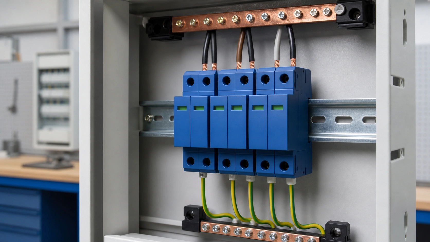
Insulation coordination at 1500 V is about matching the SPD to the bus it protects. The device must clear two conditions: its maximum continuous operating voltage (Uc) must sit above the highest sustained DC voltage of the array, and its voltage protection level (Up) must stay below the impulse withstand of the insulated equipment it feeds. Selecting a 1000 V-class SPD for a 1500 V array is a frequent field error that leaves the inverter and combiner electronics exposed.
SPD staging also follows the site lightning environment. A Type 1 + Type 2 combination is common at the array boundary where direct lightning can reach the DC side, with coordinated Uc and Up values carried consistently through the combiner box and onward to the inverter.
6. Clearance and creepage inside the enclosure
Higher voltage compresses the safety margins inside the metal enclosure. Clearance (the air distance between live parts) and creepage (the surface distance along insulation) must be specified for 1500 V plus the expected transient overvoltage. Practical consequences:
Getting these distances wrong shows up as tracking, arcing and premature failure that no fuse or SPD can correct after the fact.
- Terminal spacing and barriers must be redesigned; a 1000 V layout cannot simply be reused.
- Pollution degree and enclosure IP rating drive the required creepage distance — coastal or desert sites demand more margin.
- Internal wiring and busbar supports must use insulation rated for the 1500 V working voltage.
Technical diagram shown at a readable responsive scale.
7. Standards (IEC 62548-1, IEC 61643-31, IEC 60269-6, IEC 62446)
Specifying and verifying to these standards is what separates a compliant 1500 V combiner assembly from a generic enclosure. Confirm each rating on the datasheet before release.
- IEC 62548-1 — PV-array design requirements including DC wiring, electrical protection and switching.
- IEC 61643-31 — surge protective devices for specific application to photovoltaic installations.
- IEC 60269-6 — gPV fuses for the protection of photovoltaic systems.
- IEC 62446 — grid-connected PV systems, minimum requirements for system documentation, commissioning and inspection.
8. Specification notes for a 1500 V enquiry
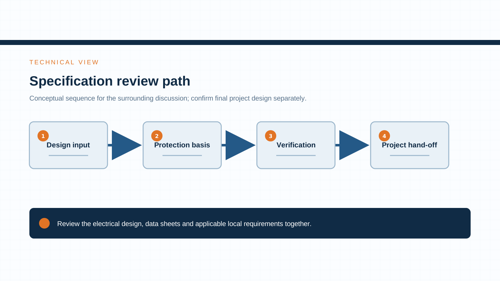
When you issue a 1500 V combiner-box or DC-protection enquiry, the numbers that decide the design are: maximum system DC voltage (1500 V), string short-circuit current including any bifacial gain, number of input strings, and the site protection and pollution class. Hand these to the supplier and the equipment you receive will be built for the array you are actually installing.
NEUTRON reviews the application context and prepares a configuration discussion around your project requirements. See the DC control and protection range and the solar PV combiner equipment range for options rated to 1500 V DC.
This is general technical guidance. Final ratings, standard editions, protection coordination and compliance evidence must be confirmed for the actual project and applicable local requirements.
Frequently asked questions
Why are utility PV plants moving to 1500 V?
Higher voltage carries the same power with less current, which reduces conductor size, lowers I²R losses and cuts the number of combiner boxes and inverters per plant. The balance-of-system savings and improved yield make 1500 V the economic default for new utility-scale arrays.
How do you rate a gPV fuse at 1500 V?
Size the fuse to at least 1.25 × the string short-circuit current per IEC 60269-6, and confirm the part is qualified for 1500 V system voltage with the required interruption rating. A gPV fuse rated only for 1000 V is not valid on a 1500 V string.
What SPD do I need for a 1500 V array?
Select an SPD per IEC 61643-31 whose maximum continuous operating voltage (Uc) exceeds the array’s highest sustained DC voltage and whose voltage protection level (Up) stays below the impulse withstand of the protected equipment. A 1000 V-class SPD will not protect a 1500 V bus.
Which standards cover 1500 V PV DC protection?
The key references are IEC 62548-1 (combiner assemblies), IEC 61643-31 (PV SPDs), IEC 60269-6 (gPV fuses) and IEC 62446 (system documentation, commissioning and inspection).
Bring the project inputs to the first review.
NEUTRON reviews the application context and prepares a configuration discussion around project requirements and the applicable document package.
Discuss a projectContinue learning
Explore related technical guidance in Electrical Protection.

Technical note: confirm the applicable standard edition, project design basis, local requirements and evidence package before final equipment selection or release.