
1. The grid-connection chain in a utility PV plant
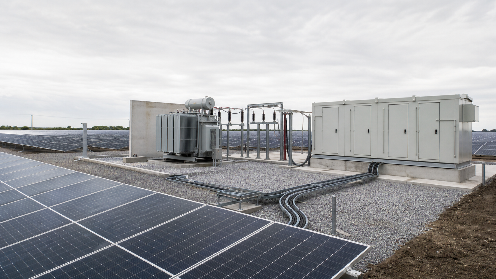
A large PV plant is assembled as a sequence of conversion and collection stages. At the array, strings feed combiner boxes that consolidate DC current. From there, collector lines carry that energy to a central step-up substation, where transformers raise the voltage and switchgear connects the plant to the grid. Ring main units (RMUs) and other switchgear manage how feeders are switched and protected along the way. Each stage has its own voltage level, protection philosophy and equipment envelope, and the whole chain must be specified as one system rather than as independent purchases.
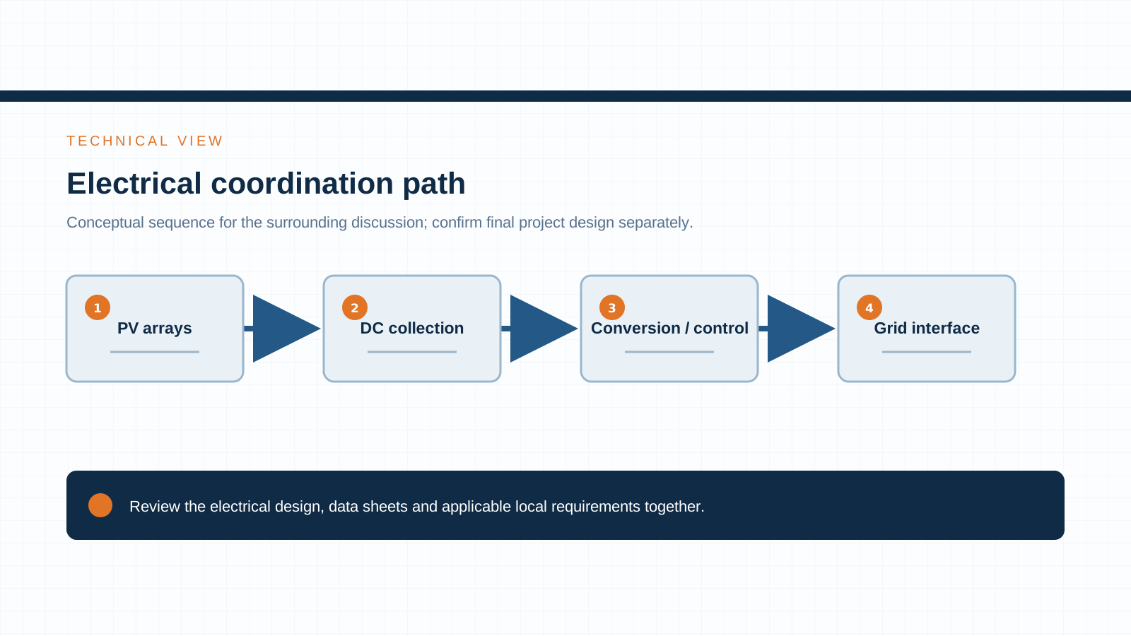
Seen end to end, the path is: PV modules and strings → combiner box → collector line → step-up substation (RMU / switchgear + transformer) → grid. The equipment NEUTRON supplies — prefabricated substations, solar PV combiner equipment and ring main units — maps directly onto the middle and upper stages of this chain.
2. Combiner box role at the array level
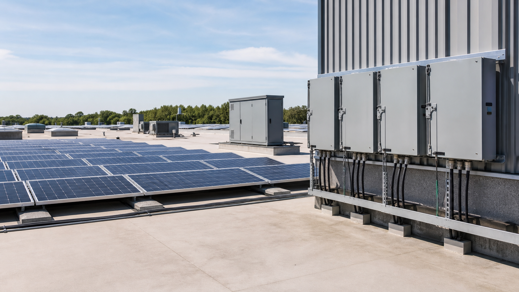
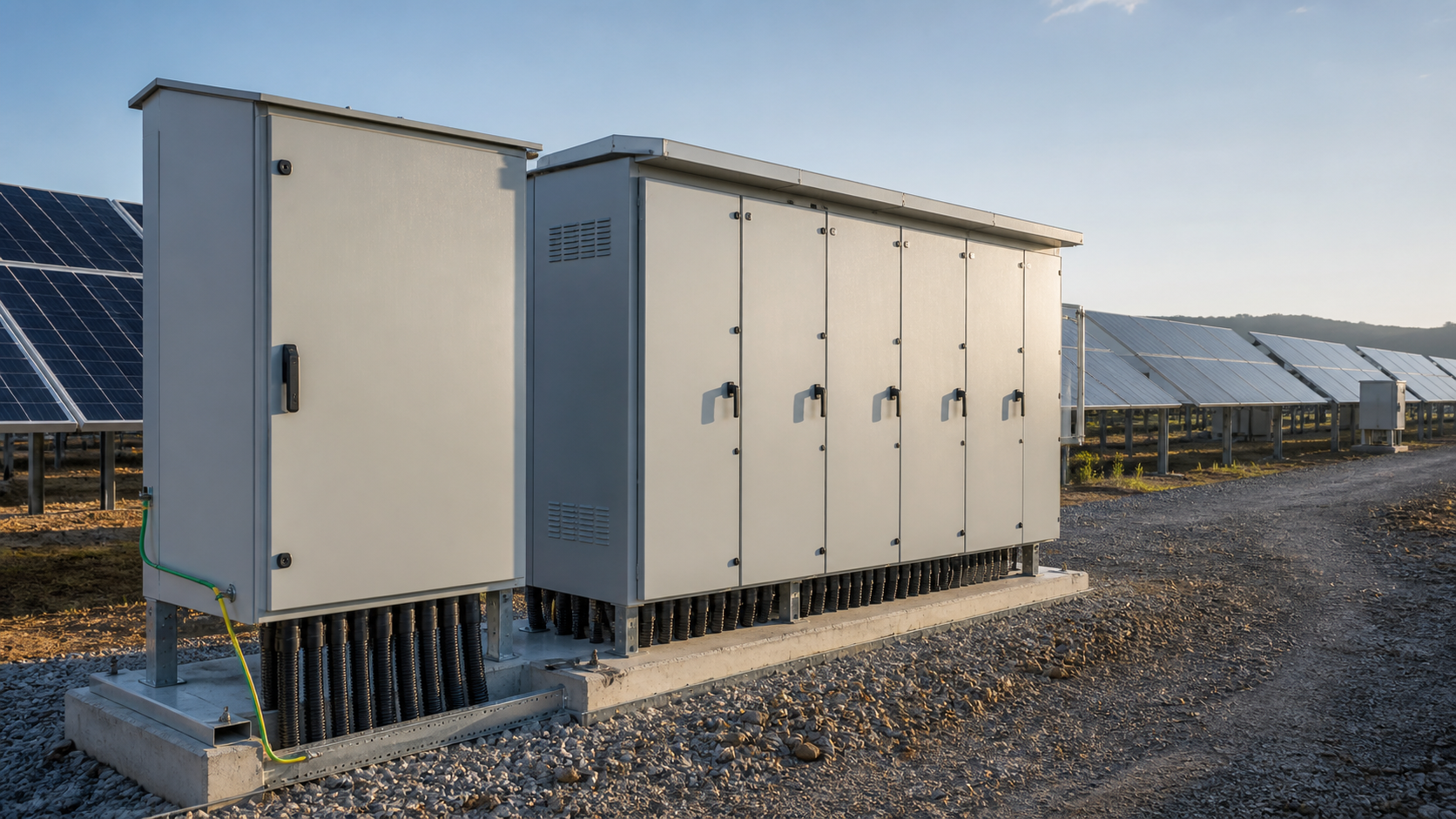
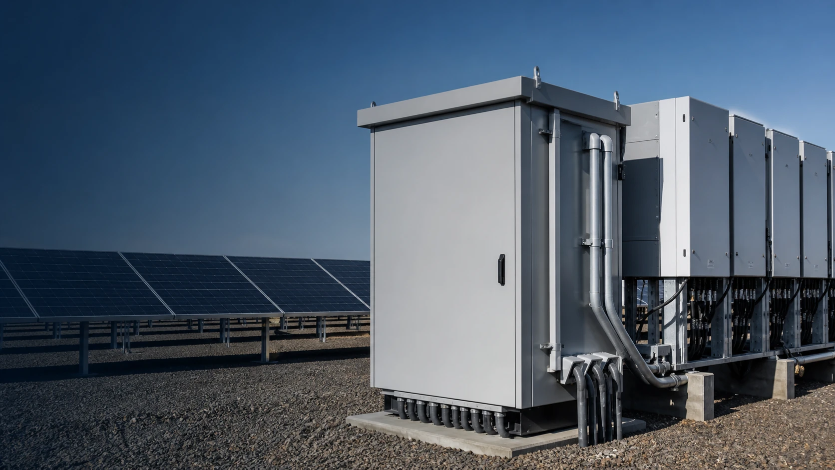
The PV combiner box is the first consolidation point. It gathers the output of multiple DC strings, protects each one with a dedicated gPV fuse and a DC disconnect, and presents a single higher-current DC feed toward the inverter or collector system. In a 1500 V array, the combiner box must be built for the higher insulation level, with an SPD stage matched to the DC envelope and busbars rated for the summed string current.
Because combiner boxes sit outdoors across the full site, their enclosures must handle the site environment — dust, moisture, corrosion class and thermal load. NEUTRON solar PV combiner equipment is sized against the projected string count and per-string short-circuit current before release, so the protection is matched to the array rather than to a generic layout.
3. Collector lines and the step-up substation
From the combiner boxes, energy travels along collector lines — the medium-voltage feeders that collect DC-acquired power (post-inverter) or, in some topologies, route DC — toward the step-up substation. The collector system is a radial or looped network sized for the aggregated plant current and the voltage drop across the site. Cable sizing, protection settings and grounding all have to be coordinated with the substation they feed.
The step-up substation is where the plant meets the grid. It houses power transformers that raise the collector voltage (commonly 35 kV) up to the grid voltage (commonly 110 kV or higher), plus the switchgear, protection and metering needed for a safe interconnection. Energizing the substation and commissioning the collector lines are the milestones that precede full grid connection of the plant.
4. Ring main units and switchgear at the substation
Within the substation, ring main units provide compact, sealed medium-voltage switching. An RMU lets operators isolate and switch collector feeders, loop the network, and localize faults without de-energizing the entire plant. For a utility PV site, RMUs are valued for their small footprint, sealed-gas or solid insulation, and fast fault clearance — all useful where space and reliability are at a premium.
NEUTRON ring main units are specified to the substation single-line diagram: rated voltage, short-circuit withstand, feeder count and protection type. They sit between the collector feeders and the step-up transformer, forming the switchgear layer that makes the substation operable and serviceable.
Technical diagram shown at a readable responsive scale.
5. Voltage levels: 1000/1500 V array side to 35 kV / 110 kV grid side
Utility PV spans several voltage steps. The array side runs at 1000 V or 1500 V DC, set by the module and string design. Inverters convert this to AC, typically at the collector voltage of 35 kV. The step-up substation then transforms 35 kV to the grid interconnection voltage, often 110 kV, depending on the host network.
Each voltage transition is a deliberate engineering choice: higher array voltage reduces current and cable loss, while the 35 kV collector bus balances cost and reach across the site. The transformer and its tap range must match both sides, and the insulation coordination has to be consistent from the combiner box through to the grid terminal.
Technical diagram shown at a readable responsive scale.
6. Protection coordination across the chain
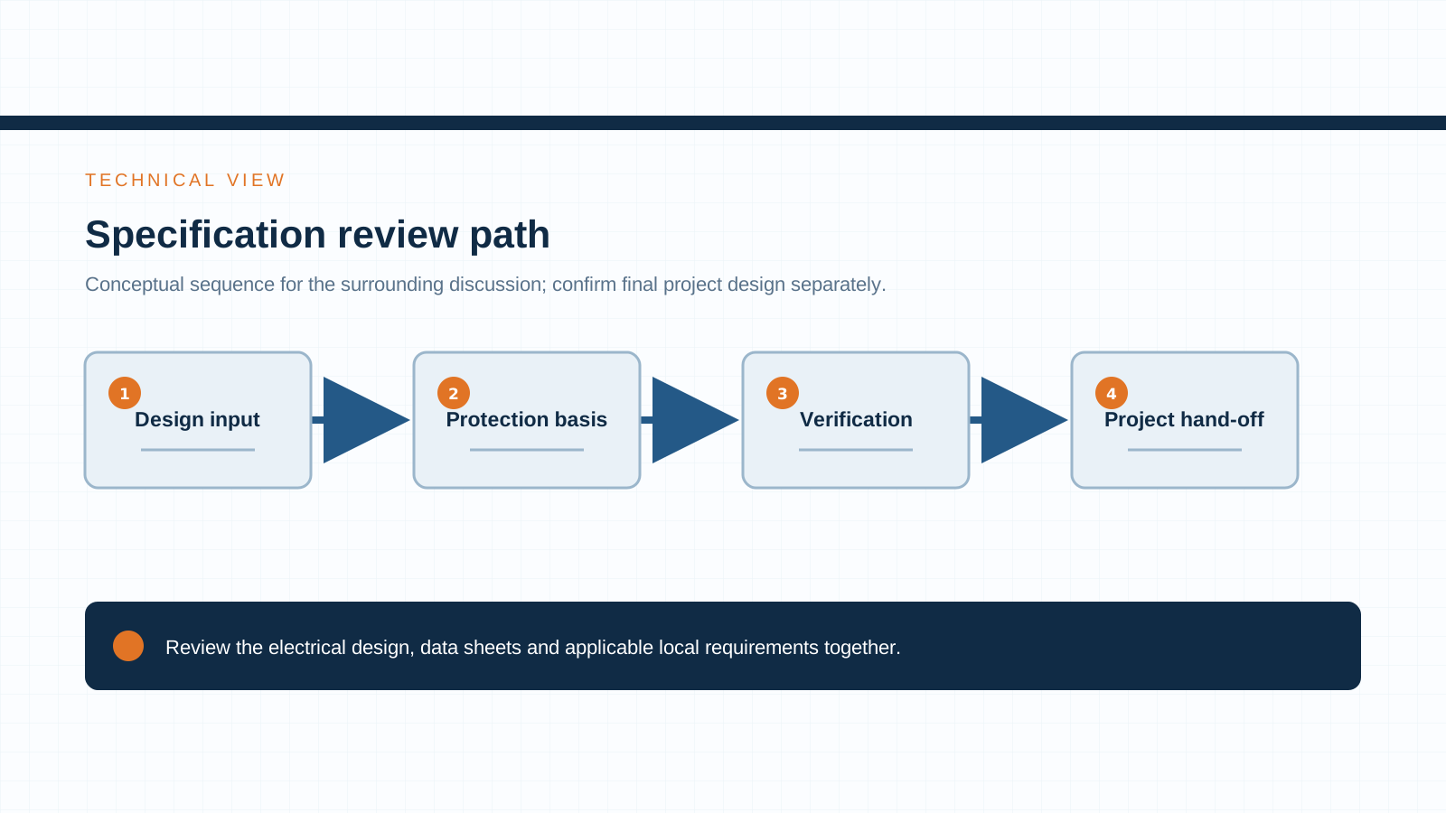
Protection has to be coordinated stage by stage so that a fault clears at the nearest device without tripping the whole plant. The gPV fuse at the combiner box protects the string; downstream fuses, circuit breakers and the RMU protect collectors and feeders; transformer and grid-side protection cover the step-up stage. Selectivity — making sure only the faulted section drops out — depends on consistent rating and setting across the chain.
A common commissioning problem is mismatched protection between equipment supplied by different vendors. Specifying the combiner box, RMU and substation together, against one single-line diagram, keeps the coordination study coherent and reduces the risk of nuisance trips during energization.
7. Relevant standards (IEC 62271, IEC 61439, IEC 61439-8)
Verifying these standards on every datasheet is what separates a compliant interconnection from a collection of mismatched enclosures. NEUTRON prepares equipment against the applicable standard for each stage of the chain.
- IEC 62271 — high-voltage switchgear and controlgear, covering the substation switching and the RMU / switchgear ratings.
- IEC 61439 — low-voltage switchgear and controlgear assemblies, governing combiner box and enclosure assemblies.
- IEC 61439-8 — assemblies for use in photovoltaic installations.
- IEC 61643-31 and IEC 60269-6 — SPDs and gPV fuses for PV protection across the DC side.
8. A specification discussion checklist for EPCs
When an EPC issues an enquiry for a grid-connection equipment package, the numbers that decide the design are: array DC voltage (1000 V or 1500 V), collector voltage (commonly 35 kV), grid interconnection voltage (commonly 110 kV), aggregate plant capacity, number of collector feeders, and the site environment class. With these, the combiner boxes, RMUs and step-up substation can be configured as one coordinated package.
NEUTRON reviews the single-line diagram and application context, then prepares a configuration discussion around your project requirements — from the array combiner box through the ring main unit to the prefabricated step-up substation. See the Solar PV product range for the equipment options.
This is general technical guidance. Final ratings, standard editions, protection coordination and compliance evidence must be confirmed for the actual project and applicable local requirements.
Frequently asked questions
What equipment connects a PV plant to the grid?
The chain runs from array combiner boxes that consolidate DC strings, through collector lines, into a step-up substation with ring main units and transformers, and finally to the grid interconnection point. Each stage collects, protects and raises the voltage toward the network.
What does a step-up substation do in solar?
The step-up substation transforms the plant collector voltage (commonly 35 kV) up to the grid voltage (commonly 110 kV or higher) and houses the switchgear, protection and metering needed for a safe grid interconnection. Energizing it precedes full plant grid connection.
Where does a ring main unit fit in a PV plant?
The ring main unit sits inside the step-up substation between the collector feeders and the step-up transformer. It provides compact medium-voltage switching so operators can isolate, loop and protect feeders without de-energizing the whole plant.
How are voltage levels stepped up in utility PV?
The array runs at 1000 V or 1500 V DC, the inverter outputs AC at the 35 kV collector level, and the step-up substation transformer raises that to the grid voltage, often 110 kV, at the interconnection point.
Bring the project inputs to the first review.
NEUTRON reviews the application context and prepares a configuration discussion around project requirements and the applicable document package.
Discuss a projectContinue learning
Explore related technical guidance in Solar PV.
Technical note: confirm the applicable standard edition, project design basis, local requirements and evidence package before final equipment selection or release.