
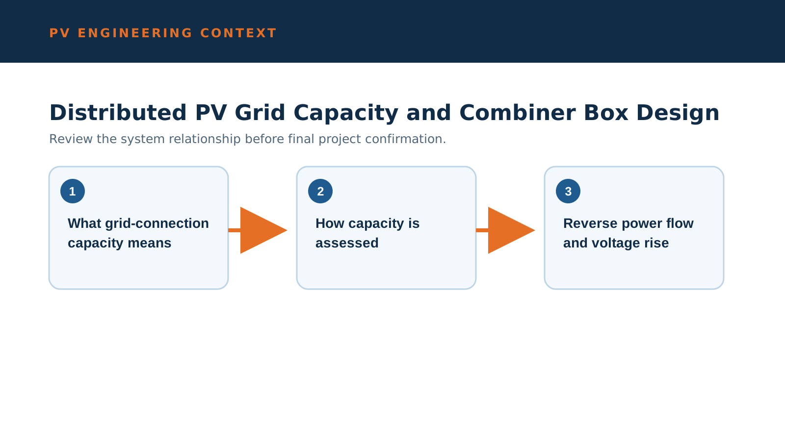
1. What grid-connection capacity means
Grid-connection capacity is the amount of distributed PV a local network segment can accept without exceeding voltage, thermal or protection limits. It is published by the network operator, often per district and per quarter.
When a segment is near its limit, new rooftop projects face constraints that shape both the system layout and the equipment specification.
2. How capacity is assessed
Operators assess the hosting capacity of a feeder using load profile, existing generation, conductor thermal rating and voltage regulation headroom. The result is a remaining available capacity figure.
That figure, not the rooftop area, often decides how large a PV system can be connected at a given point.
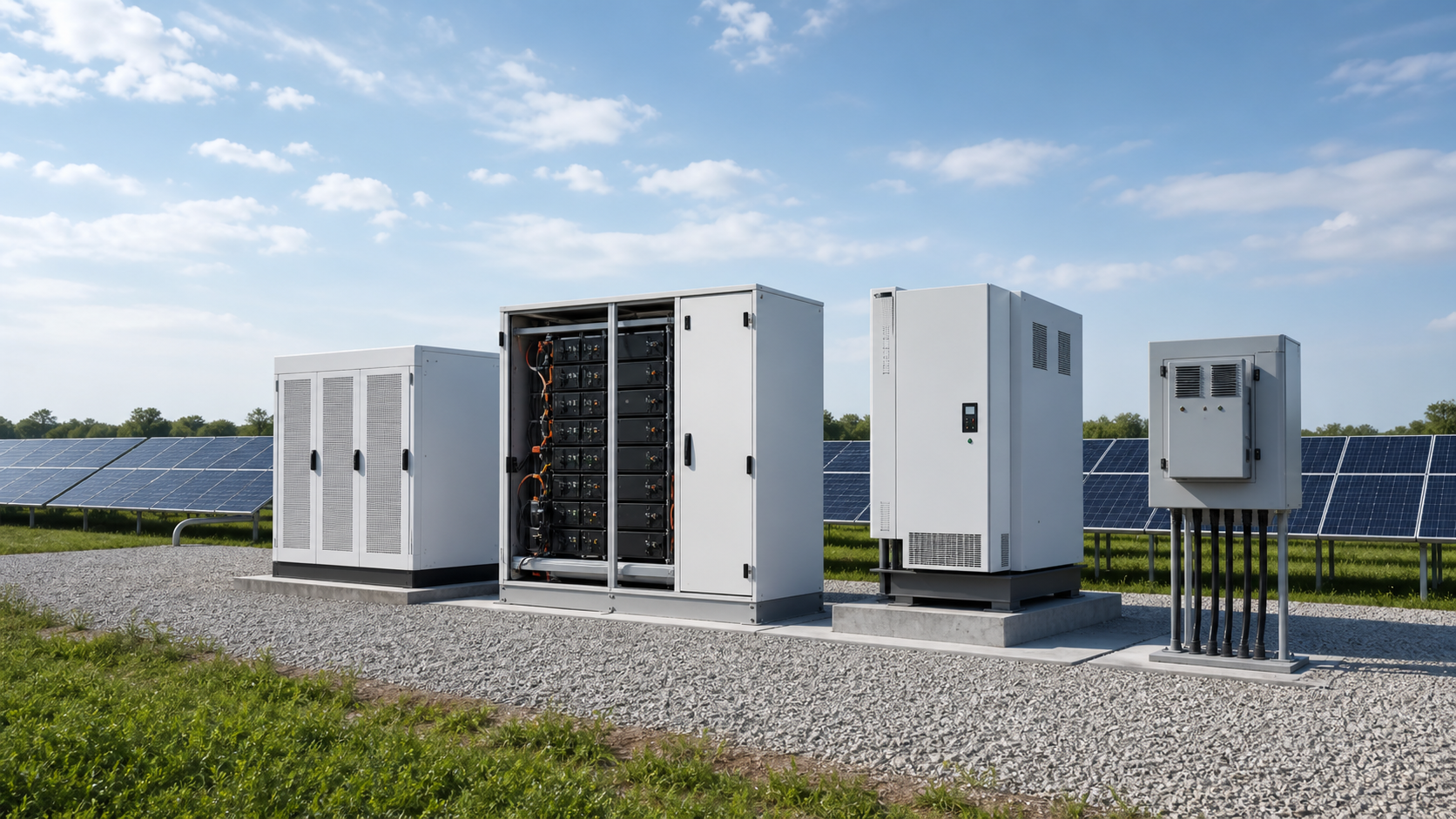
Technical diagram shown at a readable responsive scale.
3. Reverse power flow and voltage rise
PV injects active power toward the network. On a lightly loaded feeder this reverse flow can push voltage above the allowable band at the far end.
The combiner and the grid-connected cabinet must be specified so that protection and metering reflect bidirectional power, not just consumption.
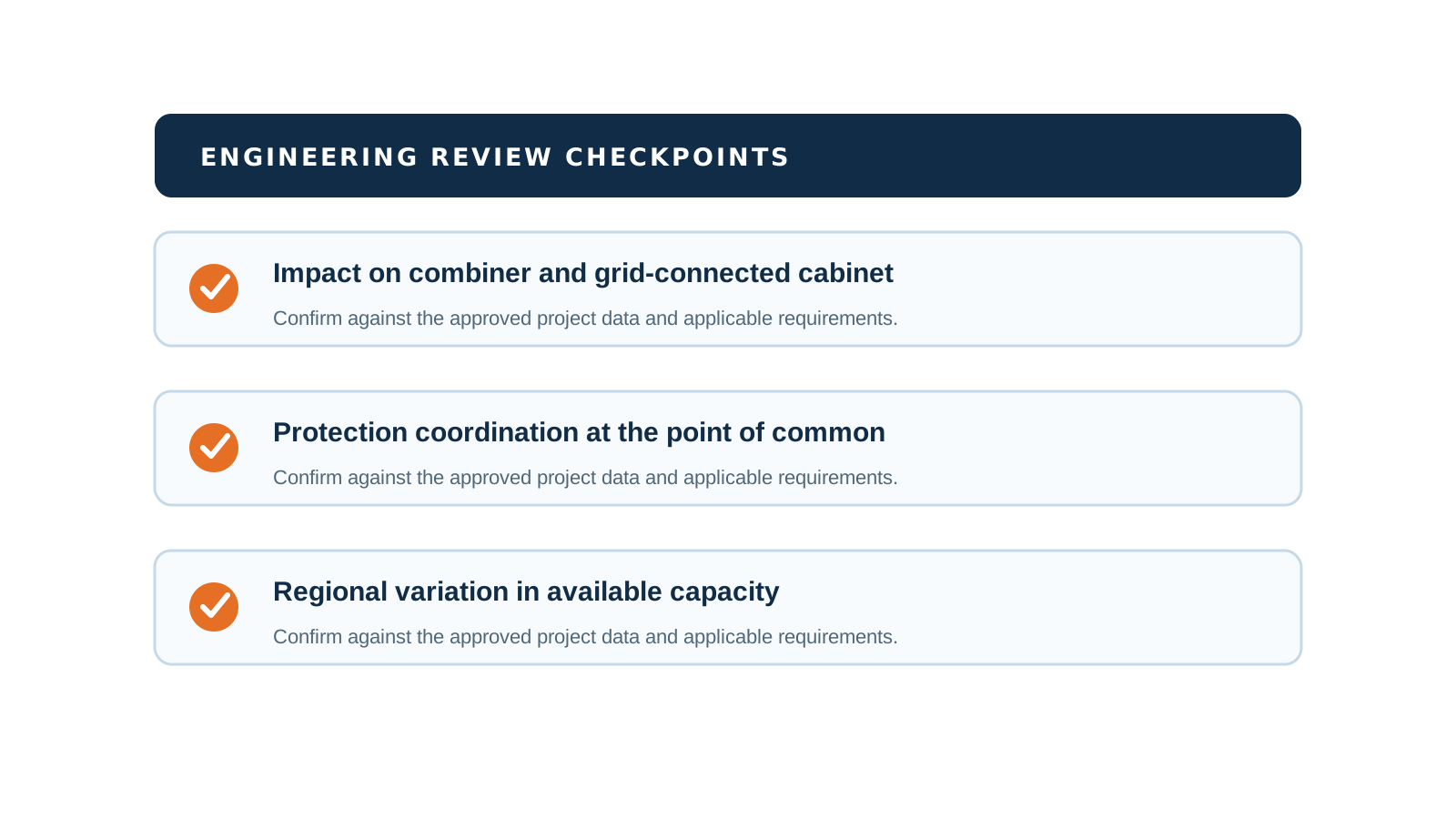
4. Impact on combiner and grid-connected cabinet
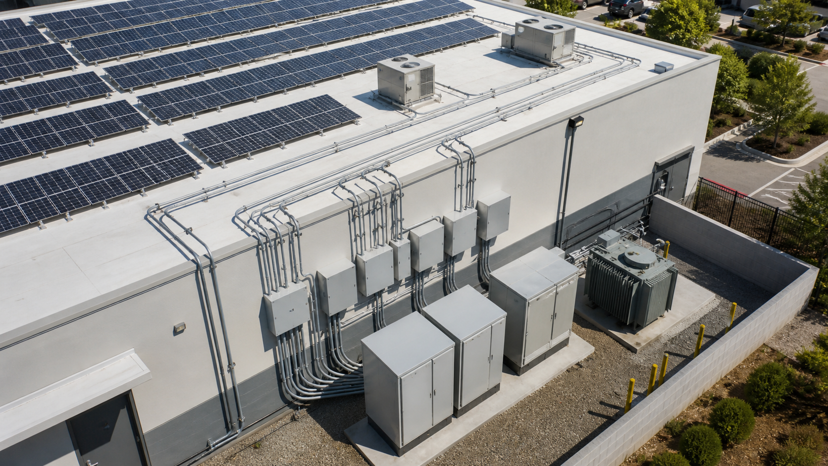
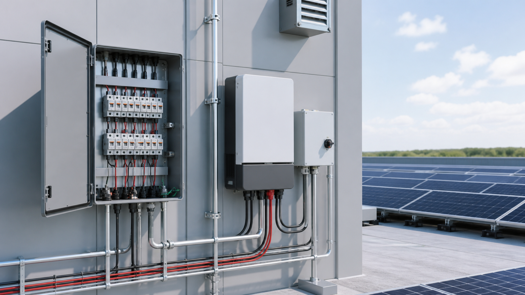
As penetration rises, the design emphasis moves from simple collection to controllable, measurable interfaces. The combiner box still fuses and isolates each string; the grid-connected cabinet handles the network interface and the isolation point.
NEUTRON sizes both so the DC collection and the AC interface remain coordinated as capacity limits tighten.
5. Protection coordination at the point of common coupling
At the point where the PV meets the network, protection must clear faults in either direction and avoid nuisance tripping of adjacent customers. Directional and sensitive settings matter more on constrained feeders.
The disconnecting means and the overcurrent devices on both sides of the interface should be selected together, not in isolation.
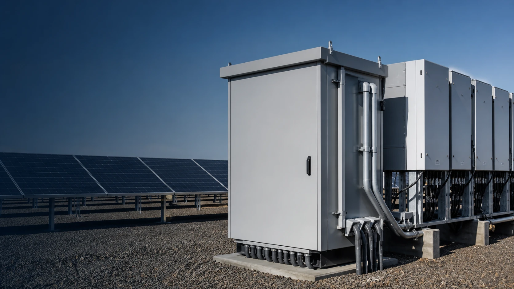
Technical diagram shown at a readable responsive scale.
6. Regional variation in available capacity
Available capacity differs sharply by district because it depends on local load, conductor size and prior connections. One district may show ample headroom while a neighbouring district is effectively full.
Treat the published figure as the binding constraint and design the array to fit it.
7. Designing for constrained feeders
On tight feeders, consider load management, smaller per-phase imbalance, and equipment that supports monitoring so the operator can verify behaviour after connection.
A combiner and grid-connected cabinet that expose string and interface data make commissioning and ongoing compliance far easier.
8. Specification takeaways
Start from the available capacity figure, then size the combiner and grid-connected cabinet for bidirectional power and coordinated protection. Confirm the point-of-common-coupling requirements before releasing the equipment list.
NEUTRON supports the discussion around combiner and grid-connected interface design for distributed PV.
This guide supports an initial technical review. Final ratings, standards, protection coordination, monitoring interfaces and configuration must be confirmed for the actual project requirement.
Frequently asked questions
What is distributed PV grid capacity?
It is the remaining amount of rooftop or local PV that a network segment can accept without breaching voltage, thermal or protection limits, usually published per district.
How does limited capacity affect design?
It caps the connectable system size and pushes the design toward controllable, measurable interfaces with protection coordinated for bidirectional power flow.
Why does reverse flow matter?
PV injects power toward the network and can raise voltage at the far end of a lightly loaded feeder, so protection and metering must account for power moving in both directions.
What equipment sits at the point of common coupling?
Typically the grid-connected cabinet with its disconnecting means and overcurrent protection, downstream of the combiner box that collects and fuses the PV strings.
Bring the project inputs together
Use the technical inputs in this guide to prepare a clear project discussion.
Discuss a projectContinue learning
Explore related technical guidance in Solar PV.
Technical note: final ratings, standards, protection coordination, monitoring interfaces and configurations remain subject to the agreed project requirement.