
What a PV Combiner Box Actually Does
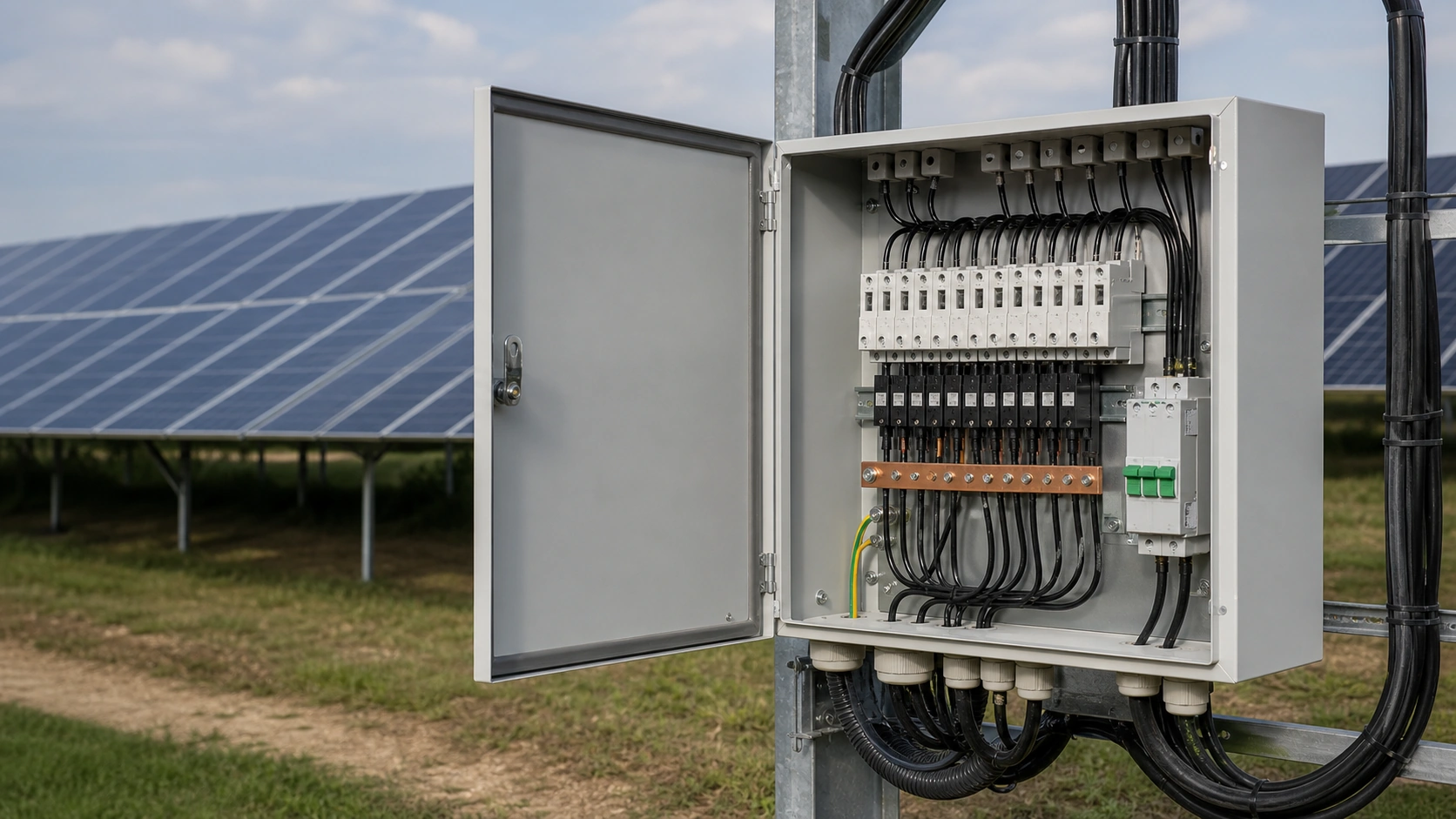
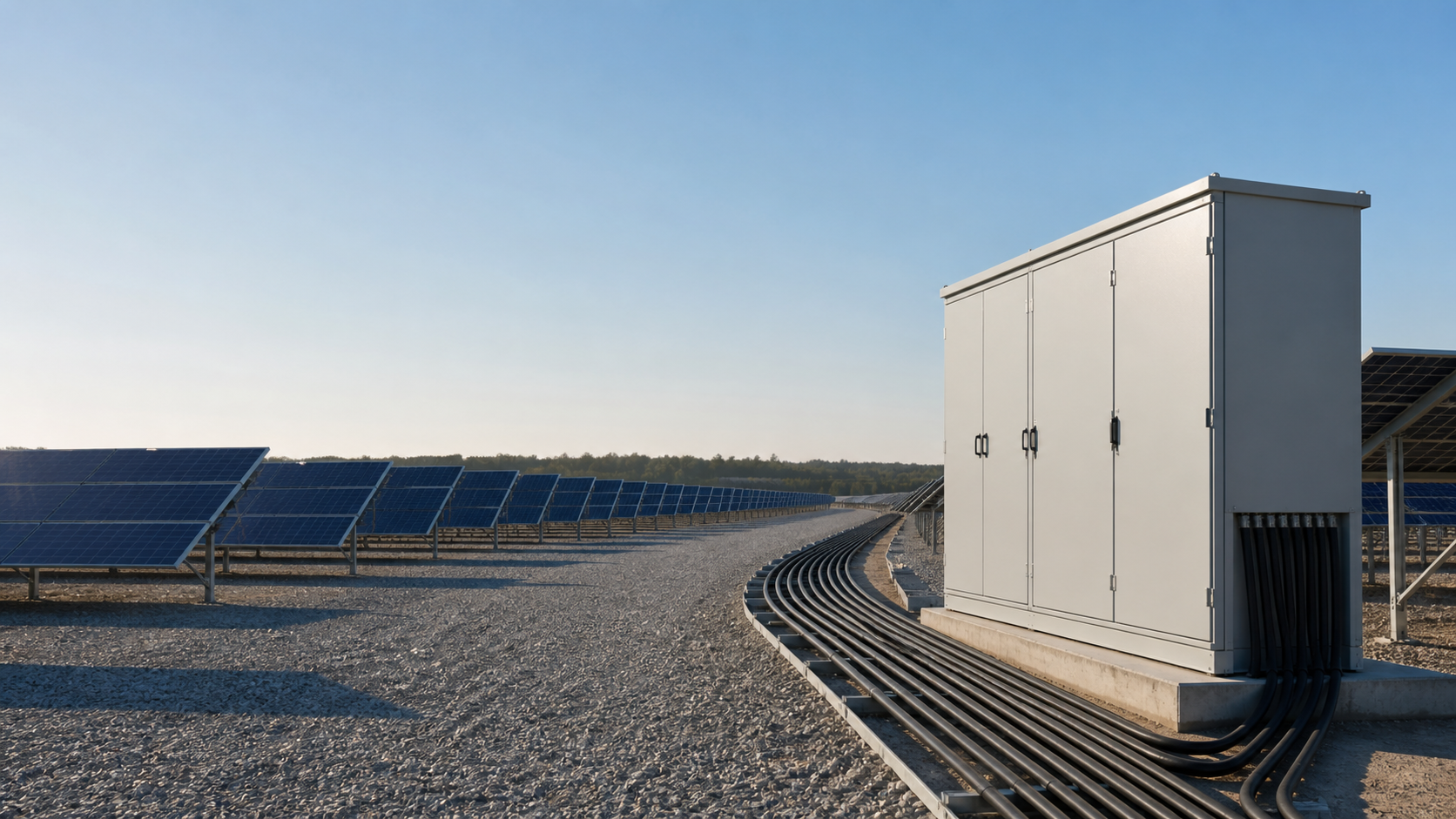
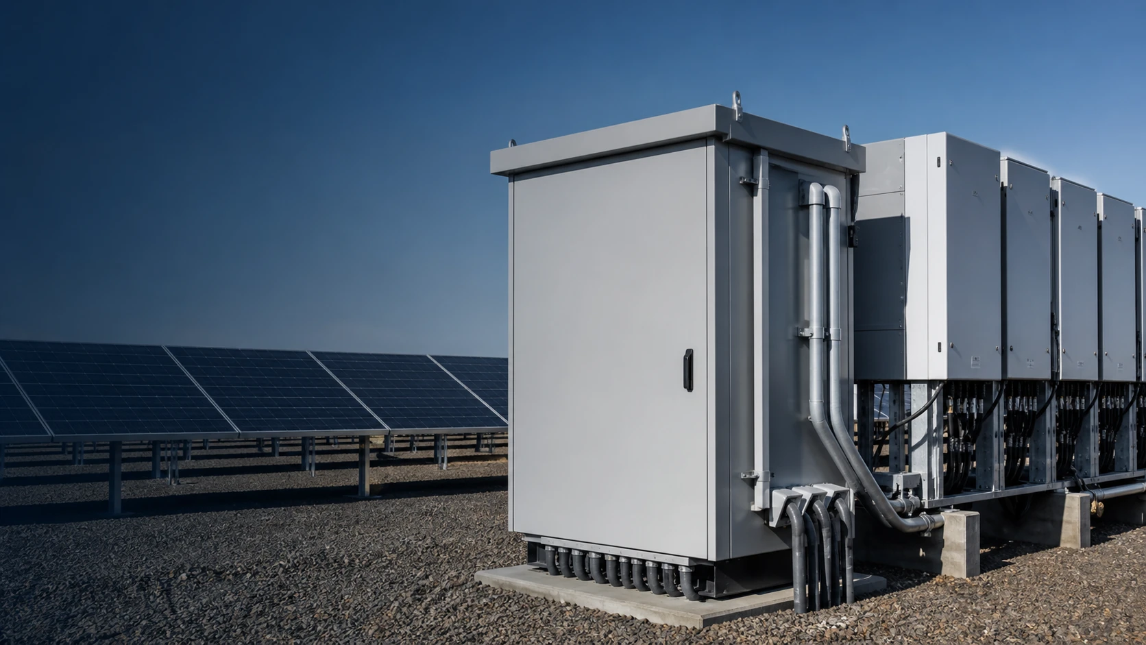
A PV combiner box sits between the array and the inverter. It accepts multiple strings, protects each string, and merges them onto a higher-current DC output so fewer cables run back to the inverter.
Typical functions are string aggregation, per-string gPV overcurrent protection, DC surge protection, safe isolation and optional current, bus-voltage or SPD-status monitoring over RS485 / Modbus-RTU. It is a safety device before it is a wiring convenience: an under-specified DC enclosure can create arc-fault exposure that AC-side protection will not clear.
- Typical commercial configurations use 4–24 inputs.
- Fuses must be PV-rated and coordinated with reverse current from parallel strings.
- A DC-rated load-break disconnector allows safe array isolation for service.
Step 1: Fix the System Voltage — 1000 V or 1500 V
Maximum system voltage determines creepage and clearance, fuse selection, SPD continuous operating voltage, terminal geometry and enclosure layout. A 1000 V box cannot simply be relabelled for 1500 V duty.
Calculate the open-circuit voltage at the coldest expected cell temperature. Uoc rises as temperature falls, so string length must be checked against the site minimum temperature rather than an annual average.
| Design factor | 1000 V DC | 1500 V DC |
|---|---|---|
| Typical application | Rooftop, C&I and distributed generation | Utility-scale ground mount and solar farms |
| Typical inputs | 4–16 strings | 8–24 strings |
| Fuse range | 10–25 A gPV | 15–32 A gPV |
| Clearance / creepage | Set by pollution degree and design | Larger distances and wider terminal pitch |
Step 2: Match String Inputs to Output Current
The per-string input rating and aggregate output rating are related but not identical. The output busbar, disconnector, cable gland and enclosure temperature each impose a limit.
- Start with the module Isc at STC and apply the 1.25 factor used for continuous PV duty.
- Multiply the fused string current by the number of inputs to obtain the theoretical output current.
- Apply ambient derating; an enclosure at elevated internal temperature will not carry its reference-ambient busbar rating.
- Select the output disconnector and busbar at the derated figure and check the cable gland for the resulting conductor size.
Source example: 16 strings at 11.5 A Isc lead to a 15 A gPV fuse selection and a calculated aggregate current of 184 A; a 250 A output disconnector and busbar above 250 A provide design headroom subject to the full project study.
Step 3: Specify the Protection Package
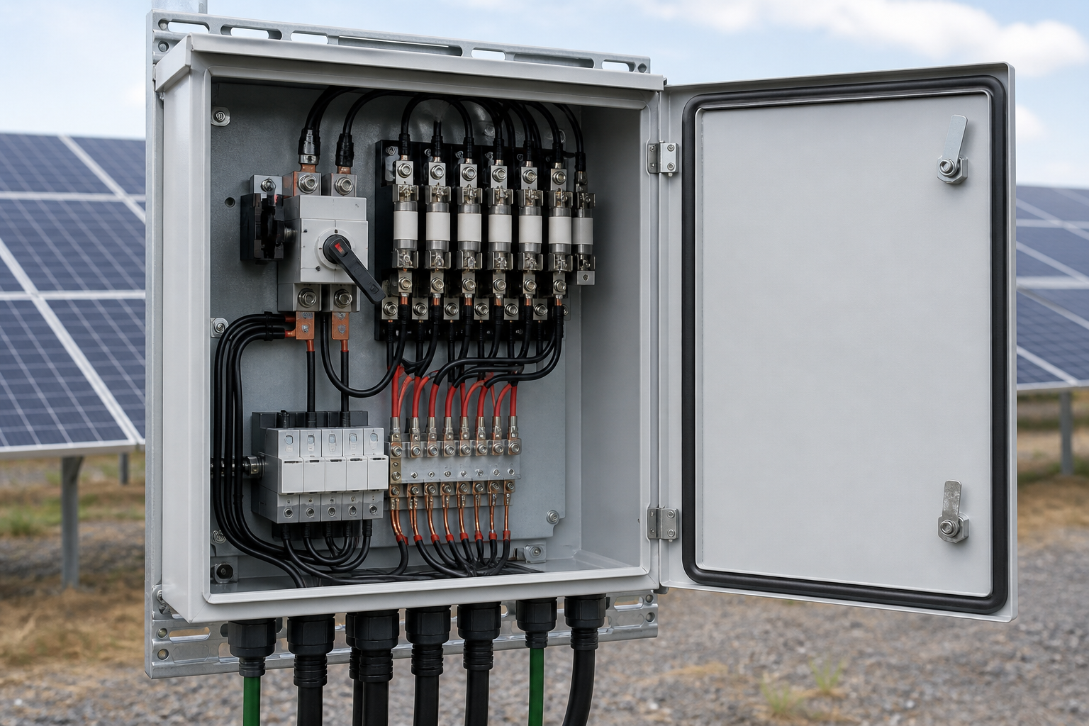
Use gPV-class fuses. General-purpose gG fuses rely on an AC current zero crossing and are not a substitute for DC-rated protection. On an ungrounded array, both positive and negative poles should be addressed according to the approved design.
The output stage normally includes a DC SPD protecting both polarities, with continuous operating voltage above the array requirement and a thermal disconnector with visible fault indication. Where the array is inside a structure with an external lightning-protection system, the entry-point surge class must follow the lightning-risk design.
A load-break DC switch-disconnector allows the array to be isolated under load; pulling fuse carriers from a live circuit is not an acceptable service method.
Step 4: Choose the Enclosure for the Site
Protection class must reflect the actual environment, not a copied catalogue line. IP20 can suit a controlled inverter room, IP54 is a common outdoor minimum and IP65 is appropriate for sand, dust, salt or aggressive industrial atmospheres when all cable entries and spare knockouts are sealed accordingly.
Material and finish also matter. Powder-coated steel is common for general duty; stainless steel may be required for severe coastal or chemical exposure. A sun shield and light-coloured finish can reduce internal temperature rise, but busbar and fuse ratings still need derating.
Step 5: Decide Whether Monitoring Pays Back
String-level monitoring adds cost per box but can pay back on large, remote or availability-sensitive plants. Useful signals include per-string current, bus voltage, SPD status and communications health.
Where monitoring is fitted, specify the acquisition accuracy, alarm behavior, protocol and register map before ordering. Retrofitting communication into an installed outdoor box is more expensive than defining it in the original drawing.
Factory Testing and Documents to Demand
Request the routine test record with the goods. A useful inspection record covers general enclosure and terminal inspection, insulation resistance, earth continuity, clearance and creepage, fuse coordination, SPD ratings, monitoring functions, IP sealing and the schematic/document pack.
- Confirm PV+, PV− and PE terminal marking and protective bonding.
- Verify insulation resistance and earth continuity against the ordered design.
- Check gPV fuse rating, SPD Uc/In and thermal-disconnector indication.
- Verify RS485 / Modbus-RTU communication and monitoring accuracy where fitted.
- Confirm gland sealing, door operation, packing list and certificate of conformity.
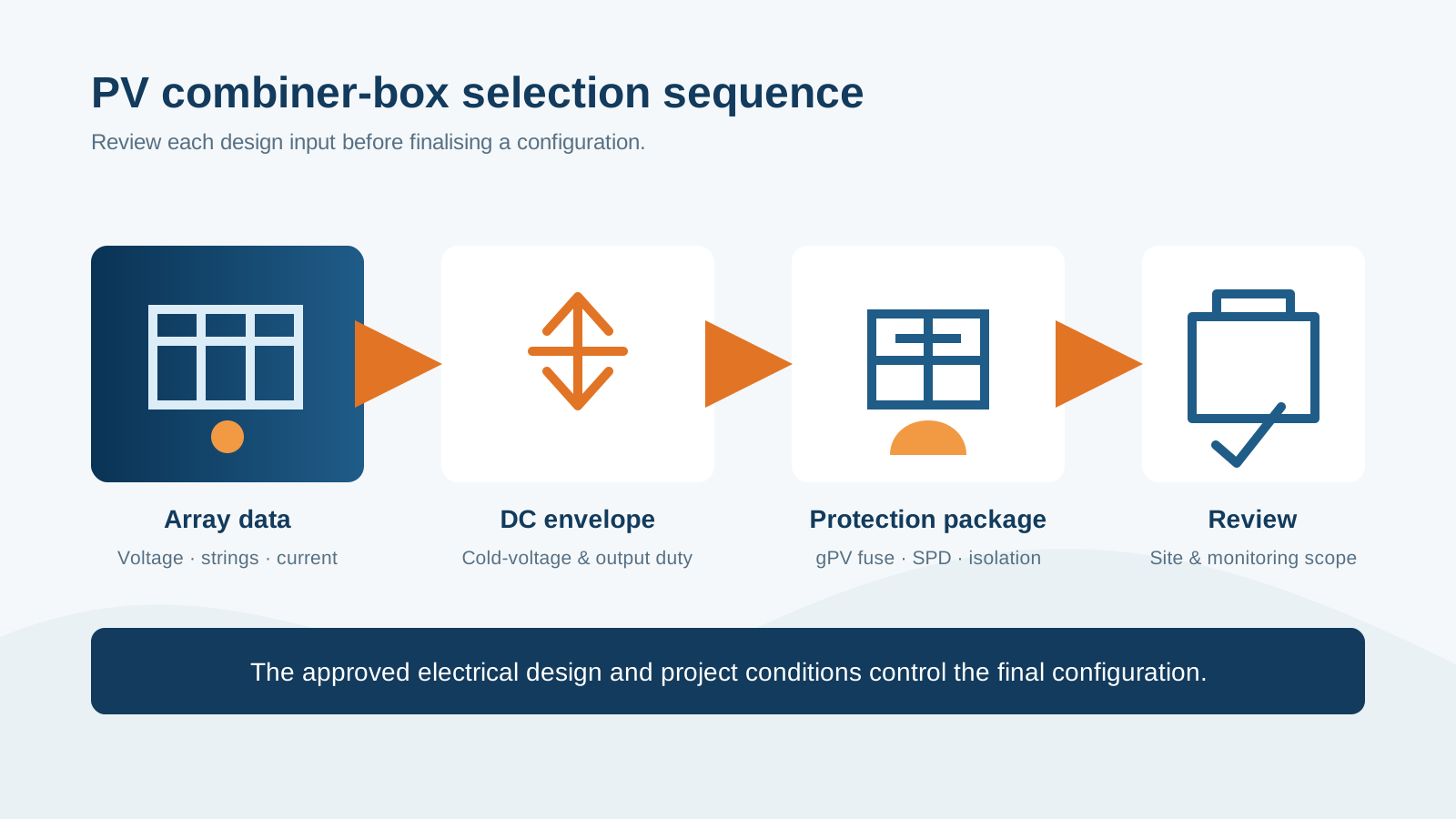
Technical diagram shown at a readable responsive scale.
Common Specification Mistakes
- Using AC-rated fuses, SPDs or isolators on the DC side.
- Sizing fuses on Impp rather than the module Isc basis required by the design.
- Ignoring cold-morning Uoc and internal temperature rise.
- Buying IP65 but installing oversized glands, unsealed knockouts or untorqued covers.
- Omitting the SPD disconnector or leaving no spare string ways.
Configuration Options in the Source Brief
The source brief describes configurable PV DC and AC combiner boxes, grid-connected cabinets and downstream PV step-up compact substations. Parameters include system voltage, string inputs, output current, protection class, enclosure material, mounting, gPV fuses, DC SPD, load-break isolation, monitoring and label language.
Provide the array datasheet, string layout, minimum site temperature, protection class and destination market so the final configuration and drawing can be reviewed before quotation.
PV arrays remain live in daylight. This guide does not replace lockout/tagout, the inverter manual, local code, a lightning-risk assessment or a project-specific design review.
Frequently asked questions
Do I need a combiner box on every solar installation?
No. Small arrays whose inverter has enough MPPT inputs for each string may not need one. A combiner box becomes useful when string count exceeds the inverter inputs or when aggregation reduces long DC cable runs.
What is the difference between a DC and an AC combiner box?
A DC combiner merges PV strings before the inverter using gPV fuses, DC SPDs and DC-rated isolation. An AC combiner merges inverter outputs after conversion using AC-rated protection; the components are not interchangeable.
How many strings should one combiner box handle?
Four to 24 inputs is a common commercial range. The practical limit is set by output-disconnector rating, busbar thermal capacity, cable entry and the spare ways required for future expansion.
What protection class should I specify for a desert solar plant?
IP65 is a common minimum for sand and dust exposure, with rated glands, sealed spare knockouts, corrosion-resistant hardware and appropriate thermal derating.
Which standards apply to PV combiner boxes?
The source brief references GB/T 34936-2017 and GB/T 34933-2017, with IEC 61439 assembly practice, IEC 60529 ingress protection, IEC 60947 switching devices and IEC 61643-31 for PV SPDs. Confirm the applicable market basis.
Start with the Array Data
Send your string layout, module datasheet, minimum site temperature, protection class and destination market for a configured combiner-box specification, drawing and routine-test scope.
Request a quoteContinue learning
Explore related technical guidance in Solar PV.
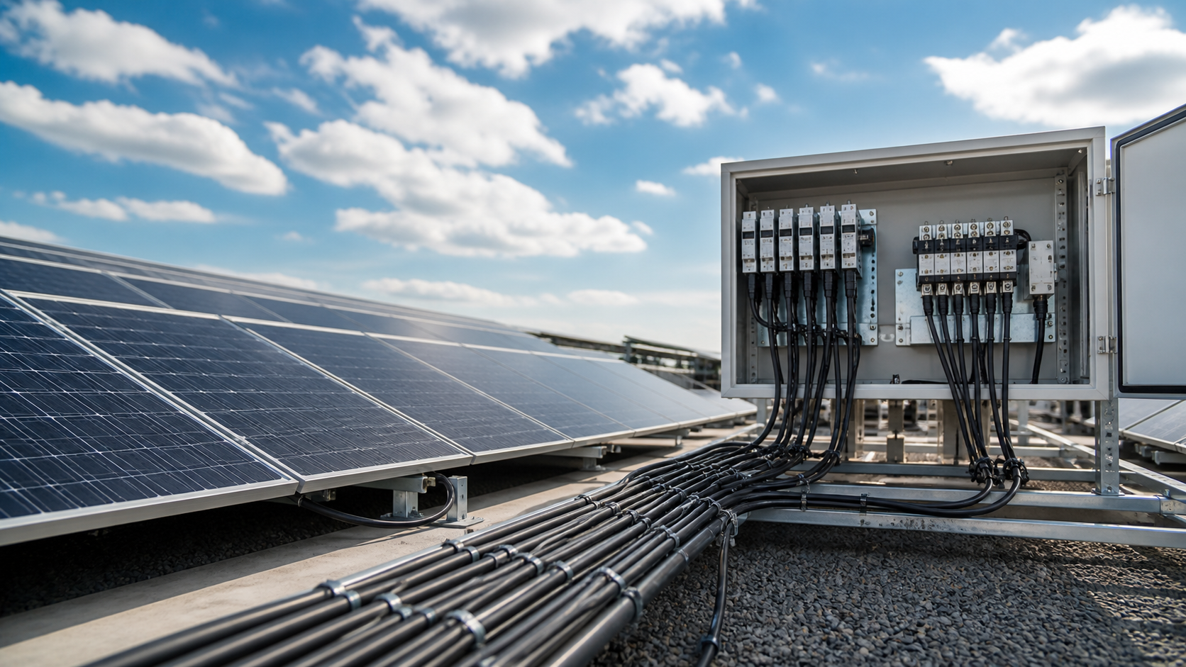
Converted from NEUTRON_PUBLISH_how-to-choose-a-solar-combiner-box_v1.0.docx. The source's selection sequence and technical examples are retained without adding external project evidence.