
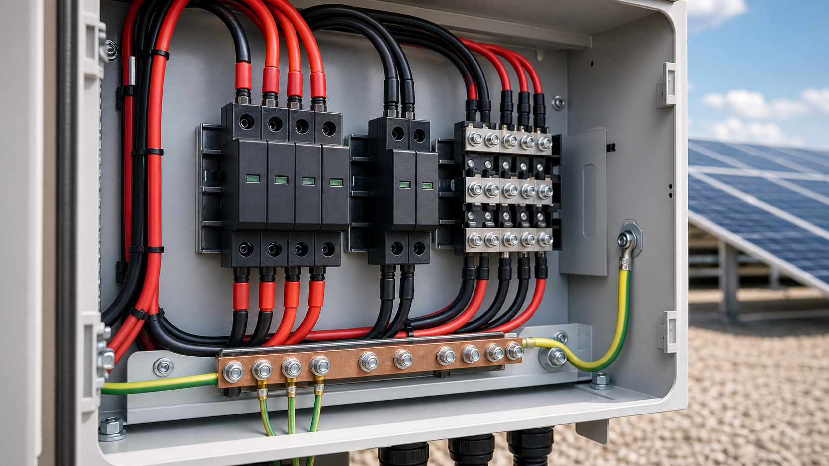
1. Why PV arrays are surge-exposed
A PV array is effectively a large, elevated conductor network spread across a field or rooftop. Three mechanisms inject overvoltage into the DC side:
Because the DC conductors often run unshielded over long distances and sit at height, the array is more exposed than most indoor low-voltage circuits. Proper DC SPD staging is the difference between a transient that is clamped safely and one that destroys a string inverter or combiner busbar.
- Direct and nearby lightning strikes couple high-energy transients into array cabling and the earthing system.
- Switching surges from inverters, DC disconnects and contactors create fast voltage steps during normal operation.
- Induced surges from distant storms travel along long DC homeruns between the array and the inverter station.
2. SPD basics for DC (Type 1 / Type 2, Up, Uc, Imax)
Selecting a PV SPD starts with four parameters that define whether it is fit for the DC side:
For PV use, the SPD is built with DC-rated modules and often includes a thermal disconnector and fault indication so a failed module de-energizes instead of burning.
- Type 1 SPD: withstands direct lightning current (10/350 µs); installed where external lightning protection is present or a strike can reach the installation.
- Type 2 SPD: limits induced and switching surges (8/20 µs); the standard choice for combiner boxes and inverter DC inputs.
- Uc (maximum continuous operating voltage): the highest DC voltage the SPD tolerates continuously. It must exceed the array open-circuit voltage (Voc) at the highest site temperature.
- Up (voltage protection level): the residual clamping voltage. It must stay below the insulation withstand of the protected equipment.
- Imax (maximum discharge current): the surge current the SPD can absorb on a single event without failure.
3. Sizing SPD for 1000 V vs 1500 V arrays
The array maximum system voltage drives the SPD voltage rating. A 1000 V system and a 1500 V system need different envelopes:
Mixing classes is the trap: a 1000 V-class SPD cannot legally or safely protect a 1500 V string, because its Uc and clearance are below the live envelope.
- 1000 V array: choose an SPD with Uc comfortably above the string Vocmax (typically a 1000 V-class or 1100 V Uc device) and Up matched to 1000 V equipment insulation.
- 1500 V array: the SPD must be a 1500 V-class device — Uc must clear the 1500 V string Vocmax, and Up must stay within the higher-voltage equipment withstand.
- Always derate for temperature: Voc rises as module temperature falls, so size Uc against the coldest expected operating condition, not the 25 °C nameplate.
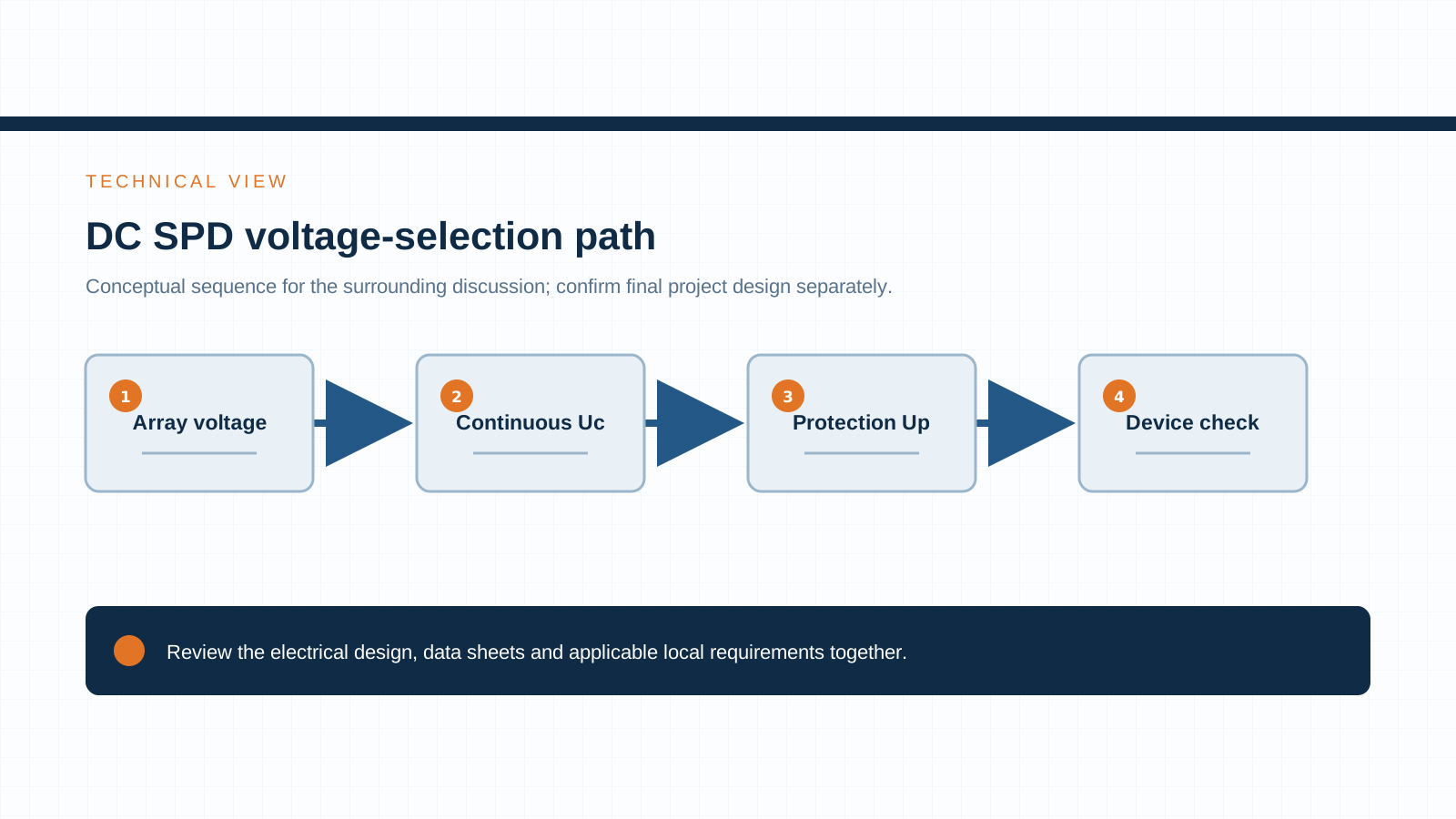
Technical diagram shown at a readable responsive scale.
4. SPD placement in the combiner box and DC side
Surge protection should sit as close as practical to the points where transient energy enters the DC circuit:
Short, thick bonding between the SPD, the DC busbar and the earthing bar keeps the clamping path impedance low — a loosely bonded SPD performs poorly no matter its rating.
- In the combiner box: a Type 2 PV SPD on each array input group or at the box DC output clamps surges before they travel toward the inverter.
- At the inverter DC input: assess a further SPD stage where cable length, equipment location and the protection design require it.
- At the array boundary: where long DC runs or high lightning density exist, a Type 1 stage at the array field limit handles direct-strike energy.
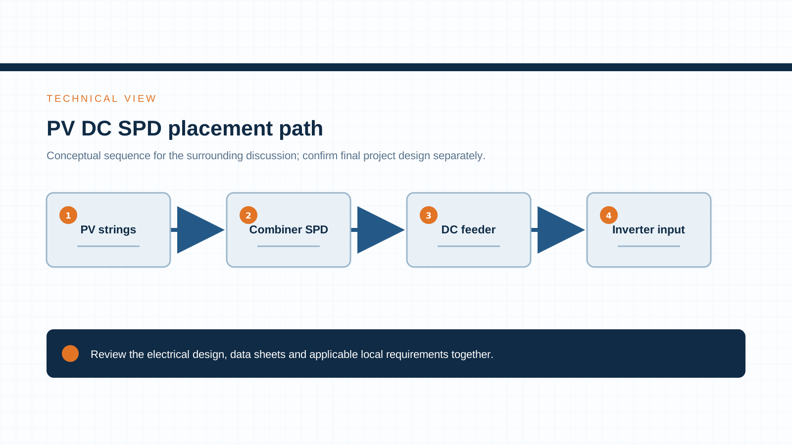
Technical diagram shown at a readable responsive scale.
5. Coordination with external lightning protection
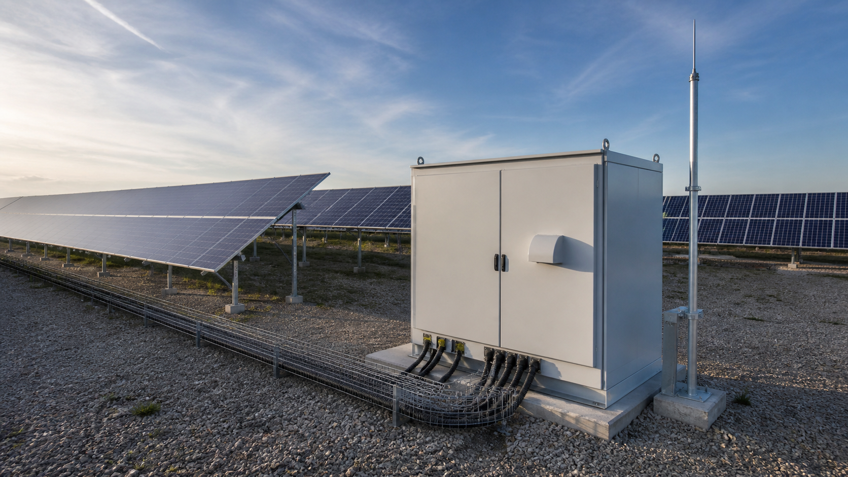
When the site has a lightning protection system (LPS) or sits in a high keraunic area, SPD staging must coordinate with it:
The goal is energy grading: each stage handles the portion of the surge it is rated for, and the final stage presents a safe voltage to the inverter.
- Select Type 1 protection only where the lightning-protection design and applicable requirements call for it.
- Type 2 SPD downstream in the combiner box and at the inverter to limit residual overvoltage.
- Shared, low-impedance earthing so the SPD discharge path does not create dangerous potential differences across the array frame and inverter chassis.
6. Common mistakes (1000 V SPD on a 1500 V array)
Field failures repeat a small set of errors:
- Installing a 1000 V-class SPD on a 1500 V array — the Uc and clearance are insufficient and the device can self-destruct under normal voltage.
- Sizing Uc from the 25 °C Voc instead of the cold-condition Vocmax, so the SPD ages or trips in winter.
- Long or thin SPD bonding leads that add inductance and raise the effective clamping voltage.
- Forgetting the DC disconnect coordination, so a tripped SPD or its thermal disconnector is not isolated safely during maintenance.
- No status indication wired to monitoring, leaving a failed SPD invisible until equipment is damaged.
7. Standards (IEC 61643-31, IEC 61643-32, IEC 62305)
PV surge protection is governed by a small set of international standards:
Specifying SPDs tested to IEC 61643-31 (not a generic AC device) and verifying the ratings on the datasheet is what separates a compliant DC installation from a makeshift one.
- IEC 61643-31 — requirements for SPDs specifically for photovoltaic applications (DC, PV-specific tests).
- IEC 62305 — lightning protection system design, including SPD coordination and risk assessment.
- IEC 61643-32 — selection, installation and coordination principles for SPDs on the DC side of photovoltaic installations.
8. SPD selection checklist
Before releasing a PV DC surge protection specification, confirm each item:
NEUTRON prepares DC control and protection configurations and power-quality equipment around your array voltage class and site risk profile; discuss the project requirements to settle the SPD stage and rating before procurement.
- System voltage class: 1000 V or 1500 V — and the correct SPD class to match.
- Uc above Vocmax at the coldest site temperature.
- Up below the insulation withstand of the combiner box and inverter DC side.
- Type 1, Type 2, or both — based on lightning protection presence and site density.
- SPD placed in the combiner box and/or at the inverter DC input with short, low-impedance bonding.
- Thermal disconnector, fault indication and monitoring wired for safe failure and visibility.
This is general technical guidance. Final ratings, standard editions, protection coordination and compliance evidence must be confirmed for the actual project and applicable local requirements.
Frequently asked questions
Type 1 vs Type 2 SPD for PV — which?
Use a Type 2 SPD in the combiner box and at the inverter DC input for induced and switching surges. Add a Type 1 SPD at the array or service boundary when an external lightning protection system is present or the site faces direct-strike risk.
What voltage SPD do I need for a 1500 V array?
A 1500 V-class PV SPD whose maximum continuous operating voltage (Uc) exceeds the string open-circuit voltage at the coldest expected temperature. A 1000 V-class device is not rated for a 1500 V system.
Where should the SPD be installed in a PV system?
At minimum in the combiner box (or per array input group) and at the inverter DC input. On high-lightning sites, add a Type 1 stage at the array boundary. Keep the bonding lead short and bonded to the earthing bar.
What does Up and Uc mean for a PV SPD?
Uc is the highest DC voltage the SPD can tolerate continuously and must exceed the array Vocmax. Up is the residual clamping voltage the SPD delivers during a surge and must stay below the equipment insulation withstand.
Bring the project inputs to the first review.
NEUTRON reviews the application context and prepares a configuration discussion around project requirements and the applicable document package.
Discuss a projectContinue learning
Explore related technical guidance in Electrical Protection.

Technical note: confirm the applicable standard edition, project design basis, local requirements and evidence package before final equipment selection or release.