
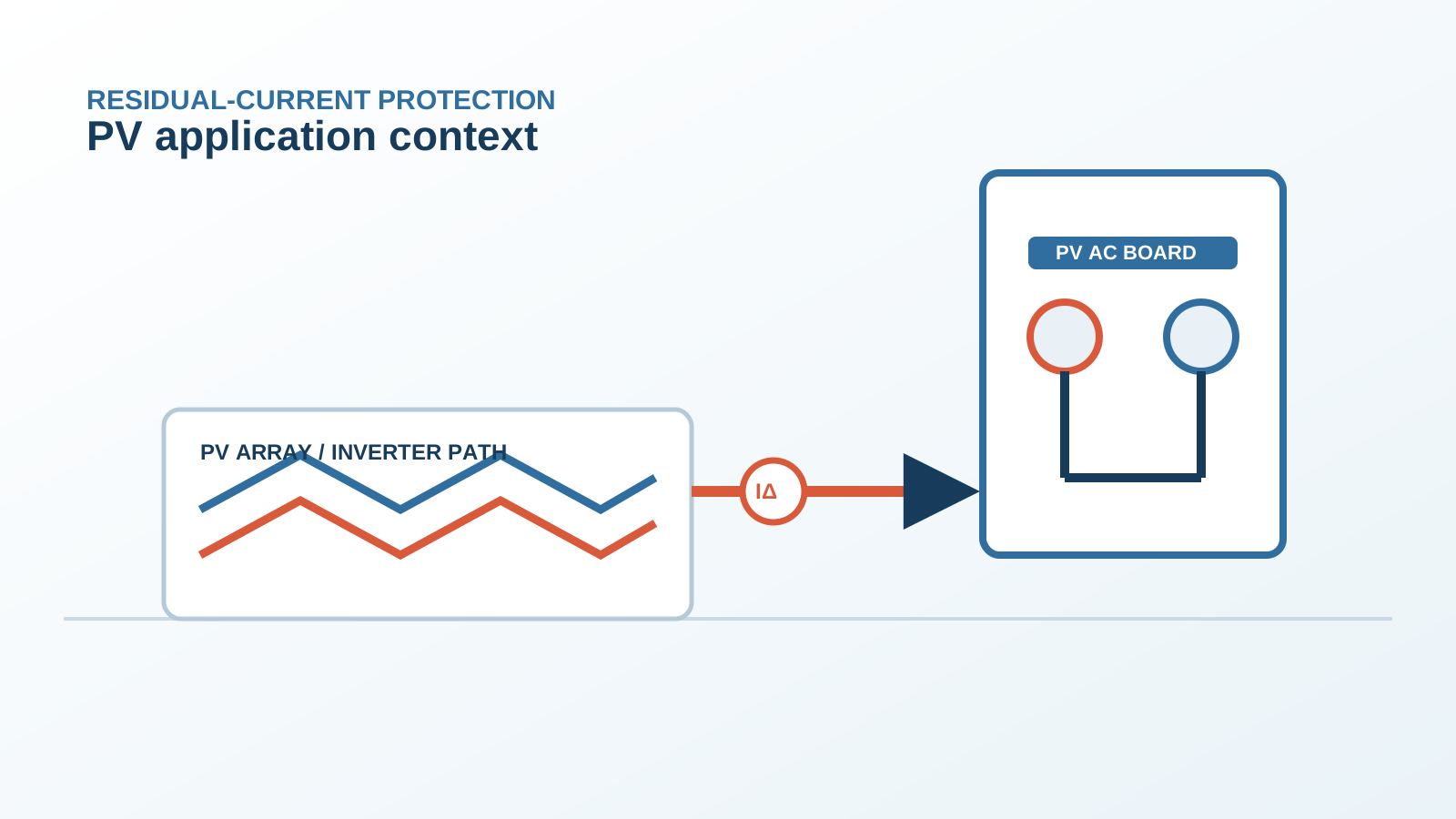
1. What happens at inverter soft-start
A grid-connected inverter does not begin exporting the instant the array reaches operating voltage. It first charges its DC link, verifies grid voltage and frequency inside the required window, checks array insulation resistance, then closes its grid relay and ramps output power over a controlled interval. Each of these steps changes the electrical relationship between the array and earth. Closing the grid relay in particular ties the floating array potential to the grid reference in one step.
The array to earth is a large capacitance, formed by every cell surface facing its earthed frame. When the potential of that capacitance is stepped, a charging current must flow through it to earth. That current is a genuine residual current as far as any protective device is concerned: it leaves through the earth path and does not return through the circuit conductors. It is also brief, and it decays as the array capacitance reaches its new steady potential.
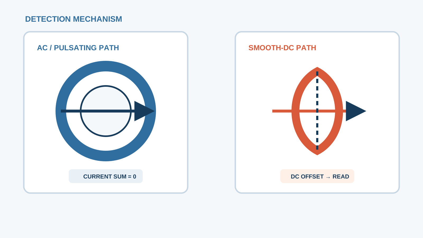
Technical diagram shown at a readable responsive scale.
2. The shape of the residual-current transient
The transient has a characteristic profile that distinguishes it from a fault. It begins with a fast peak at relay closure, decays over some tens of milliseconds to a few hundred milliseconds as the capacitance charges, and then settles into the standing leakage level for the prevailing irradiance and humidity. Superimposed on the decay is the switching-frequency common-mode current of the conversion bridge, which builds up as the power ramp proceeds.
Initial peak at grid relay closure: capacitive charging of the array to earth, amplitude scaling with array area and cable length.
Decay phase: exponential settling towards the standing leakage as the array capacitance reaches equilibrium.
Ramp phase: switching-frequency common-mode content rising with exported power.
Steady state: standing leakage governed by irradiance, humidity and insulation condition — the baseline for all later comparison.
3. Why a correctly rated Type B device should not trip
A correctly selected all-current-sensitive device is not defeated by this transient, for two reasons. First, its residual sensitivity is chosen with a documented margin above the measured standing leakage, so the transient peak has headroom to sit in. Second, a device with a short time delay characteristic will not release on a peak whose duration is shorter than its non-actuating time, which is precisely why selective and time-delayed variants exist for circuits fed by power electronics.
A device that does trip on soft-start is therefore reporting one of three things: an undersized sensitivity chosen without measuring the plant, an unnecessarily fast characteristic on a circuit that has a known inrush, or a real insulation weakness that only shows up when the array potential is stepped. The distinction is resolved by measurement, not by assumption.
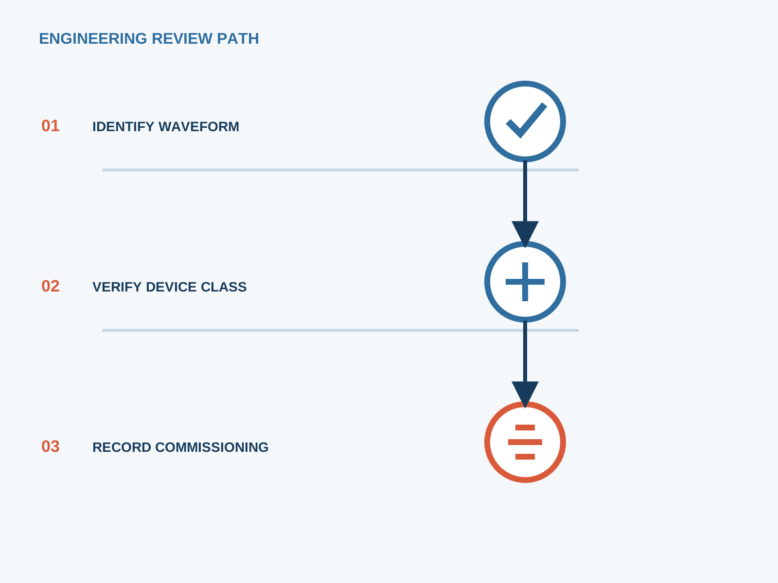
4. Mis-set sensitivity as the usual cause
The single most frequent root cause is a residual sensitivity carried over from domestic practice. A 30 mA instantaneous device is correct for a socket-outlet circuit and often wrong for a feeder serving several inverters, where the standing leakage alone may already occupy a substantial part of that budget before any transient is considered. Adding parallel inverters multiplies the standing leakage at the common upstream device while leaving each individual circuit apparently healthy.
The correct selection separates the protective objectives. Where additional protection for persons is required — maintenance socket outlets, accessible final circuits — 30 mA remains appropriate and should be applied on those circuits specifically. Where the objective on a feeder is fire protection, 100 mA or 300 mA with a short time delay both meets that objective and clears the transient comfortably.
5. Symmetrical measurement versus differential measurement
When investigating a startup trip, what is measured determines what is learned. A clamp closed around a single conductor measures load current and reveals nothing about residual current. A clamp closed around all live conductors of the circuit together — every phase and the neutral where one exists — measures the true residual, which is the quantity the device responds to. Omitting the neutral on a four-wire circuit produces a large false reading and sends the investigation in the wrong direction.
Because the event of interest is a transient, the instrument must be able to capture it. A true-RMS leakage clamp with a data-logging or peak-hold function, or a current probe on an oscilloscope, will show the peak amplitude and the decay time constant. An averaging handheld meter will simply miss the peak and report a healthy standing figure, which is why some startup trips are wrongly dismissed as unexplained.
6. Logging trips during commissioning
Record the exact time of each trip and correlate it with the inverter event log and the irradiance record.
Note whether the trip occurs at grid relay closure, during the power ramp, or at a later moment — each points to a different mechanism.
Log the standing residual current before the trip and after a successful restart.
Repeat the startup sequence several times; a transient artefact is reproducible while a developing insulation fault tends to worsen.
Test each inverter alone and then in combination to reveal accumulation at the upstream device.
Keep the array insulation resistance reading from the inverter self-test alongside the trip log.
7. Mitigation without disabling protection
Every acceptable mitigation either reduces the transient or accommodates it with a correctly characterised device. None of them involves removing, bypassing or wedging the protective device. Reducing the transient means attending to the physical causes: shortening DC runs, keeping positive and negative conductors together to limit loop area, ensuring the module frame and mounting-structure bonding is continuous and low-impedance, and confirming the DC cable insulation is dry and undamaged.
Accommodating the transient means selecting the device for the circuit: an all-current-sensitive type with a short time delay on the inverter feeder, a residual sensitivity matched to the protective objective with margin above measured leakage, and 30 mA instantaneous protection reserved for the accessible final circuits where persons are the concern. Splitting a large board so that several inverters do not share one residual-current device is often the cleanest fix of all, because it stops the leakage accumulating at a single point.
8. Acceptance test procedure
Measure and record standing residual current for each inverter circuit at full export and in damp early-morning conditions.
Verify the device by calibrated injection on every declared waveform — sinusoidal, half-wave pulsating and smooth direct — and record the tripping times.
Capture the startup transient with a logging leakage clamp or current probe and record peak amplitude and decay time.
Confirm the margin between the recorded standing leakage plus transient peak and the device residual sensitivity.
Perform ten consecutive startup cycles with no trip as the acceptance criterion.
File the complete record, including irradiance, humidity and ambient temperature, as the baseline for future maintenance comparison.
NEUTRON supplies the DC protection assemblies and low-voltage switchgear that host these devices and can review a board arrangement where startup tripping has proved persistent.
This is general application guidance. Confirm final ratings, trip settings, standards, inverter instructions and local installation requirements against approved project documentation and a qualified engineer's review.
Frequently asked questions
Why does my RCD trip only when the inverter starts?
Closing the inverter grid relay steps the potential of the array with respect to earth, and the large array-to-earth capacitance must charge through the earth path. That charging current is a real residual current, but it is brief and decays as the capacitance settles. A trip confined to startup therefore points to a transient plus insufficient margin, rather than to a standing insulation fault.
Should I raise the RCD sensitivity setting to stop the trips?
Not blindly, and never by removing protection. Choose the residual sensitivity from the protective objective: keep 30 mA instantaneous on accessible final circuits where persons are the concern, and use 100 mA or 300 mA with a short time delay on a feeder whose objective is fire protection. The chosen value must have a documented margin above the measured standing leakage.
Is a Type B device less prone to startup tripping?
It is less prone to misbehaviour, which is not quite the same thing. A Type B device measures the direct component instead of being biased by it, so its stated sensitivity is real and predictable. Avoiding startup trips comes from selecting the sensitivity with margin and using a short time delay on circuits with a known inrush.
How can I commission the plant without disabling the RCD?
Capture the startup transient with a logging leakage clamp closed around all live conductors together, measure the standing leakage at full export and in damp morning conditions, then select a device whose sensitivity and time characteristic clear the recorded peak. Splitting the board so several inverters do not share one device is often the cleanest remedy.
Bring the protection inputs to the first review.
{ "@context": "https://schema.org", "@type": "Article", "headline": "RCD Tripping Behaviour During PV Inverter Soft-Start", "description": "Why a PV RCD trips at inverter soft-start, the shape of the residual-current transient, and how to commission and mitigate it without weakening protection.", "author": { "@type": "Organization", "name": "NEUTRON LLC" }, "publisher": { "@type": "Organization", "name": "NEUTRON LLC", "logo": { "@type": "ImageObject", "url": "https://www.neutronele.com/logo.png" } }, "datePublished": "2026-09-03", "dateModified": "2026-09-03", "mainEntityOfPage": "https://www.neutronele.com/insights/rcd-tripping-curve-pv-inverter-startup", "image": "https://www.neutronele.com/insights/img/rcd-tripping-curve-pv-inverter-startup-hero.jpg", "articleSection": "Electrical Protection", "keywords": "RCD trip PV inverter startup, soft-start leakage, inrush residual current, Type B, nuisance trip, commissioning", "inLanguage": "en" }
Discuss a project requirementContinue learning
Explore related technical guidance in Electrical Protection.

Published from the approved period 10 source package; technical claims and source wording are retained for review.