
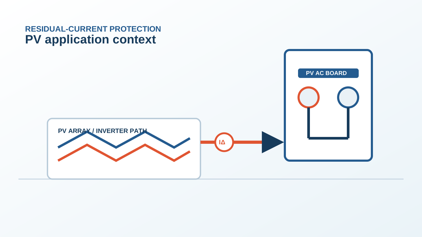
1. What a Type A RCD actually senses
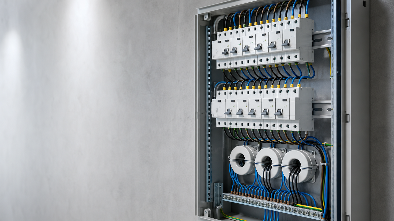
A Type A device works on a single passive principle. All live conductors of the circuit pass through a toroidal core of high-permeability magnetic material. Under healthy conditions the currents sum to zero and the net flux in the core is zero. A residual current unbalances that sum, the changing flux induces a voltage in a secondary winding, and that voltage releases a polarised tripping magnet. The critical word is changing: the mechanism responds to the rate of change of flux, not to flux itself.
That is why a Type A device covers sinusoidal residual current and half-wave pulsating direct residual current — both vary continuously — but has no mechanism at all for a steady direct current. A constant residual current produces a constant flux, a constant flux induces no secondary voltage, and the device sees nothing.
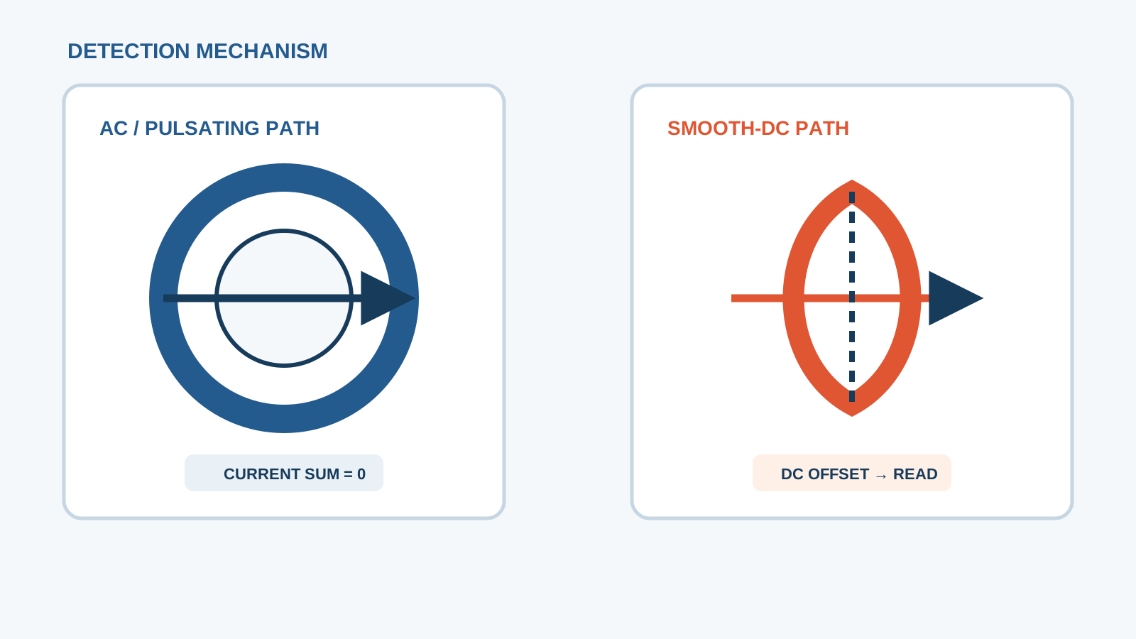
Technical diagram shown at a readable responsive scale.
2. The smooth DC component of a transformerless topology
Without a transformer there is no galvanic separation between array and grid, so the array floats on the grid potential and the parasitic capacitance of the modules to their earthed frames becomes a live path to earth. The switching bridge modulates that potential, and because the modulation is not perfectly balanced and the array polarity relative to earth is fixed, the leakage does not average to zero. What remains is a smooth direct residual current of typically a few milliamperes, rising with array area, cable length, insulation ageing and humidity.
That current is not itself a hazard at those magnitudes. Its significance is entirely indirect: it flows through the toroidal core of any residual-current device on the circuit and changes how that core behaves.
3. Core saturation and lost sensitivity
A high-permeability core has a narrow linear region. A steady direct current through the primary conductors imposes a fixed magnetisation offset that pushes the operating point away from the centre of that region and towards the knee of the magnetisation curve. The incremental permeability at the new operating point is lower, so an AC residual current of a given magnitude now produces a smaller secondary voltage than it would in an unbiased core. The device needs more residual current to reach its release threshold.
The degradation is progressive, not a clean cut-off. A modest offset raises the effective tripping current above the rated value; a larger offset can push the operating point deep enough that the AC sensitivity is lost across a wide band. This is the reason the 6 mA figure appears throughout PV standards: it marks the region where the bias becomes significant for a conventional core. A 30 mA Type A device with a several-milliampere DC bias is no longer a 30 mA device, and nothing on the front panel says so.
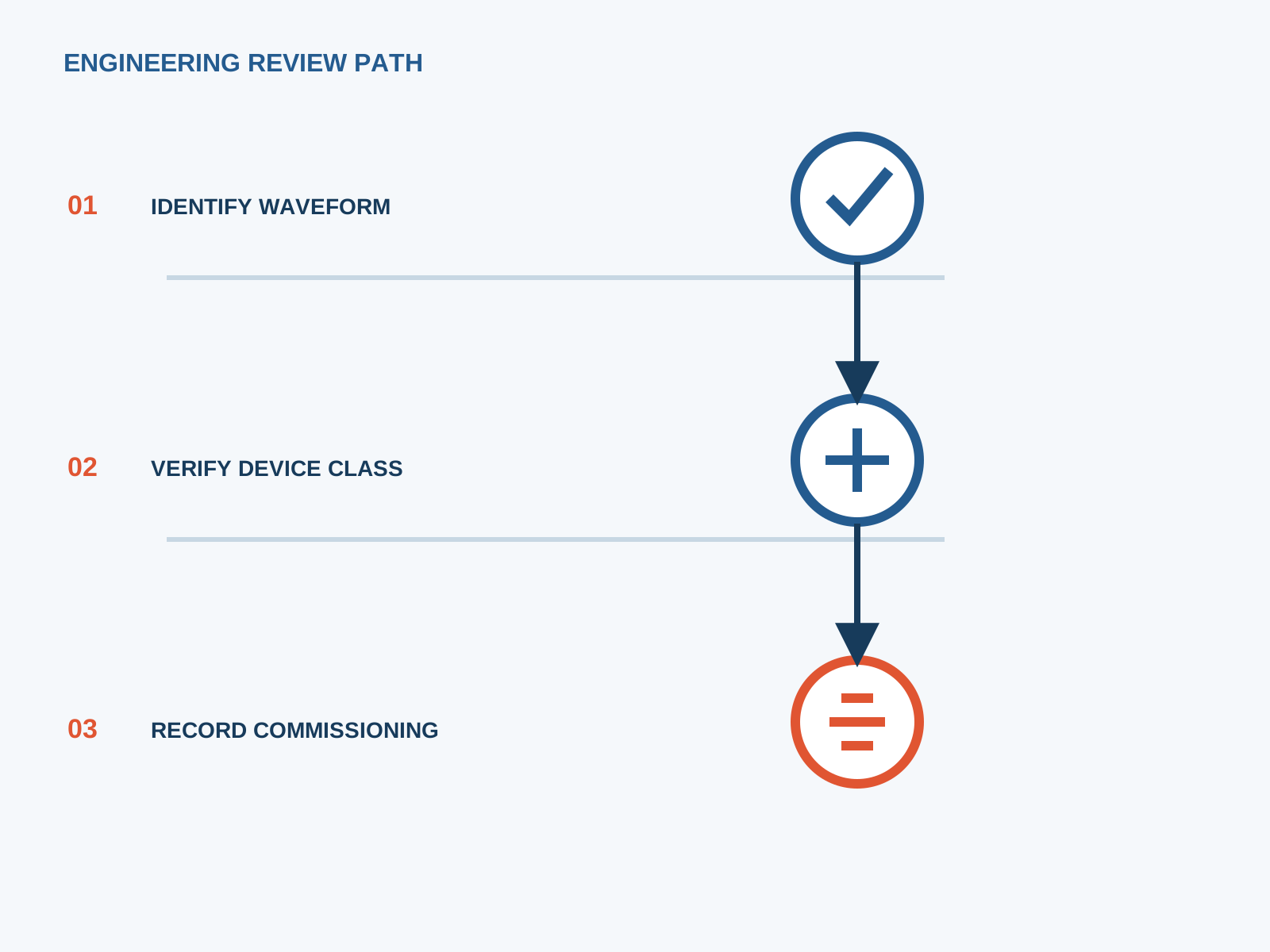
4. Field symptoms of a blinded RCD
The failure is silent by nature, so the symptoms are indirect and are usually found by measurement rather than by observation.
The test button trips the device normally — it drives a small internal current through the core and proves the release mechanism, not the sensitivity.
A calibrated injection test with the inverter running gives a tripping current above the rated residual value, while the same test with the inverter isolated passes.
Tripping times measured under the AC waveform lengthen compared with the commissioning record.
A clamp meter with true DC capability, applied around all live conductors together, reads a steady direct residual current of a few milliamperes.
In mixed installations, an identical device on a non-PV circuit passes the same test that the PV circuit device fails.
5. The standard position
The type classification of residual-current devices with direct-current sensitivity is set out in IEC 62423, which defines the Type F and Type B classes and their test waveforms, including pure smooth direct residual current. The general requirements common to all classes sit in IEC 60755, and the RCCB and RCBO product standards IEC 61008 and IEC 61009 govern construction and verification. On the equipment side, IEC 62109-2 sets the residual-current behaviour required of a grid-connected inverter, including the treatment of a steady direct component.
Read together, the framework does not say that a Type A device is forbidden on every PV circuit. It says that where a smooth direct residual current can occur, the protective device must be one whose declared performance covers it — in practice a Type B or otherwise all-current-sensitive device, unless the inverter formally declares an equivalent integrated function and the project rules accept that as the protection for that zone.
6. The correct device: Type B or all-current-sensitive
A Type B device solves the problem architecturally rather than by tolerance. It keeps the passive toroid for AC and pulsating residual current and adds a second, actively driven core whose magnetisation is swept by an oscillator. A direct residual current makes that sweep asymmetric, and the evaluation electronics turn the asymmetry into a DC measurement. The direct component is therefore measured rather than merely survived, and the AC sensitivity is preserved because the passive path is not biased into its knee region.
Where the load is a single-phase drive or pump circuit with mixed-frequency leakage but no true steady offset, a Type F device may be the proportionate answer. Where a transformerless inverter is involved, Type B is the baseline.
7. Retrofit path for existing AC boards
A retrofit is mostly a mechanical and coordination exercise, because the replacement device is usually wider and needs an auxiliary supply for its electronics.
Measure the steady direct residual current on the live circuit before changing anything, so the need is documented.
Check DIN-rail width: an all-current-sensitive device typically occupies more modules than the Type A it replaces.
Confirm the auxiliary supply arrangement and wire the status contact into the plant monitoring system.
Re-verify coordination with the upstream overcurrent device so the short-circuit withstand of the new device is still covered.
Update the board schedule, the circuit labels and the handover file to show the new type and sensitivity.
8. Verification after replacement
Verification must be done with the array live and the inverter exporting, because that is the only condition in which the direct component exists. Inject a calibrated residual current for each waveform the new device declares — sinusoidal at rated sensitivity, half-wave pulsating, and smooth direct — and record the tripping times against the manufacturer limits. Repeat the sinusoidal test with the inverter isolated; the two results should now agree, which is the direct evidence that the bias no longer affects sensitivity.
File the readings with the ambient temperature, irradiance conditions and time of day. Without those figures a later maintenance test cannot be compared, because natural array leakage varies through the day and with humidity.
This is general application guidance. Confirm final ratings, trip settings, standards, inverter instructions and local installation requirements against approved project documentation and a qualified engineer's review.
Frequently asked questions
Why does a Type A RCD not trip on PV DC leakage?
Its detection principle responds to changing magnetic flux. A steady direct residual current produces a constant flux, which induces no voltage in the secondary winding, so the device has no mechanism to detect it. Worse, that constant flux biases the core and reduces its sensitivity to the AC residual current it is supposed to detect.
Is the inverter at fault when this happens?
Usually not. A small steady direct residual current is an inherent consequence of a transformerless topology combined with module parasitic capacitance, and inverter standards permit it up to defined limits. The fault is a protection-selection error: an AC-sensing device was applied to a circuit that carries a direct component.
Does the standard framework require Type B for PV circuits?
IEC 62423 defines the Type F and Type B classes and their direct-current test waveforms rather than mandating a class per application. The requirement follows from the installation rules: where a smooth direct residual current can occur, the protective device must declare performance that covers it, which in practice means Type B or another all-current-sensitive device.
How do I verify that a replacement RCD works?
Test with the array live and the inverter exporting. Inject a calibrated residual current for each declared waveform — sinusoidal, half-wave pulsating and smooth direct — and record the tripping times. Then repeat the sinusoidal test with the inverter isolated; matching results confirm that the direct bias no longer affects sensitivity.
Bring the protection inputs to the first review.
{ "@context": "https://schema.org", "@type": "Article", "headline": "Why a Type A RCD Fails on Transformerless PV Inverters", "description": "How a smooth DC offset saturates the core of a Type A RCD on a transformerless PV inverter circuit, the field symptoms it produces, and the correct retrofit path.", "author": { "@type": "Organization", "name": "NEUTRON LLC" }, "publisher": { "@type": "Organization", "name": "NEUTRON LLC", "logo": { "@type": "ImageObject", "url": "https://www.neutronele.com/logo.png" } }, "datePublished": "2026-09-03", "dateModified": "2026-09-03", "mainEntityOfPage": "https://www.neutronele.com/insights/type-a-rcd-failure-transformerless-pv-inverter", "image": "https://www.neutronele.com/insights/img/type-a-rcd-failure-transformerless-pv-inverter-hero.jpg", "articleSection": "Electrical Protection", "keywords": "Type A RCD transformerless PV failure, saturated core, smooth DC blindness, residual current monitor, Type B requirement, IEC 62423", "inLanguage": "en" }
Discuss a project requirementContinue learning
Explore related technical guidance in Electrical Protection.

Published from the approved period 10 source package; technical claims and source wording are retained for review.