
1. Why transformerless inverters create smooth DC leakage
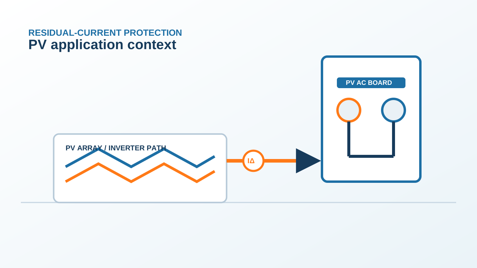
A transformerless inverter has no galvanic barrier between the photovoltaic array and the grid conductors. The array therefore rides on the grid potential, and the large parasitic capacitance between the module cells and their earthed frames becomes an electrically live path. Switching in the DC/AC bridge modulates the array potential at kilohertz rates, so a capacitive displacement current flows continuously through that path to earth. Because the bridge modulation is not perfectly symmetrical, and because the array operates at a fixed polarity with respect to earth, part of the resulting leakage does not average to zero over a mains cycle.
That non-zero average is the smooth DC residual current: a unidirectional current with negligible ripple, typically only a few milliamperes, superimposed on the AC and pulsating components. It is small, but it is exactly the quantity that determines whether an AC-only or Type A device can still function. Insulation ageing, damp module frames and long DC cable runs all increase it, and the effect scales with array area, so utility blocks see more of it than a single rooftop string.
Technical diagram shown at a readable responsive scale.
2. How a Type B RCD detects AC, pulsating and smooth DC residual current
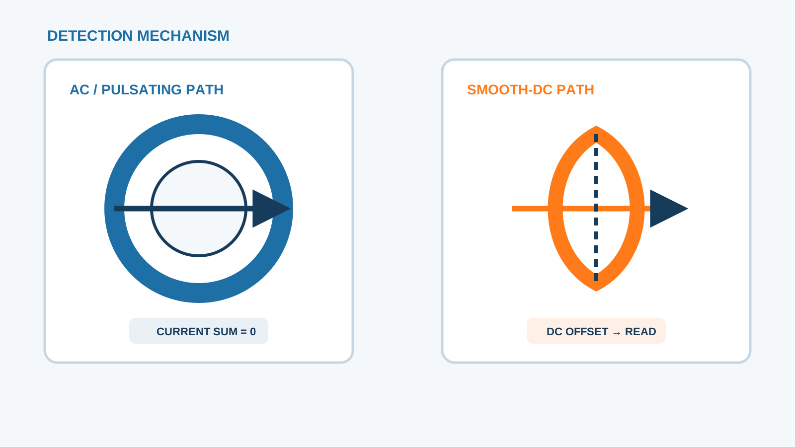
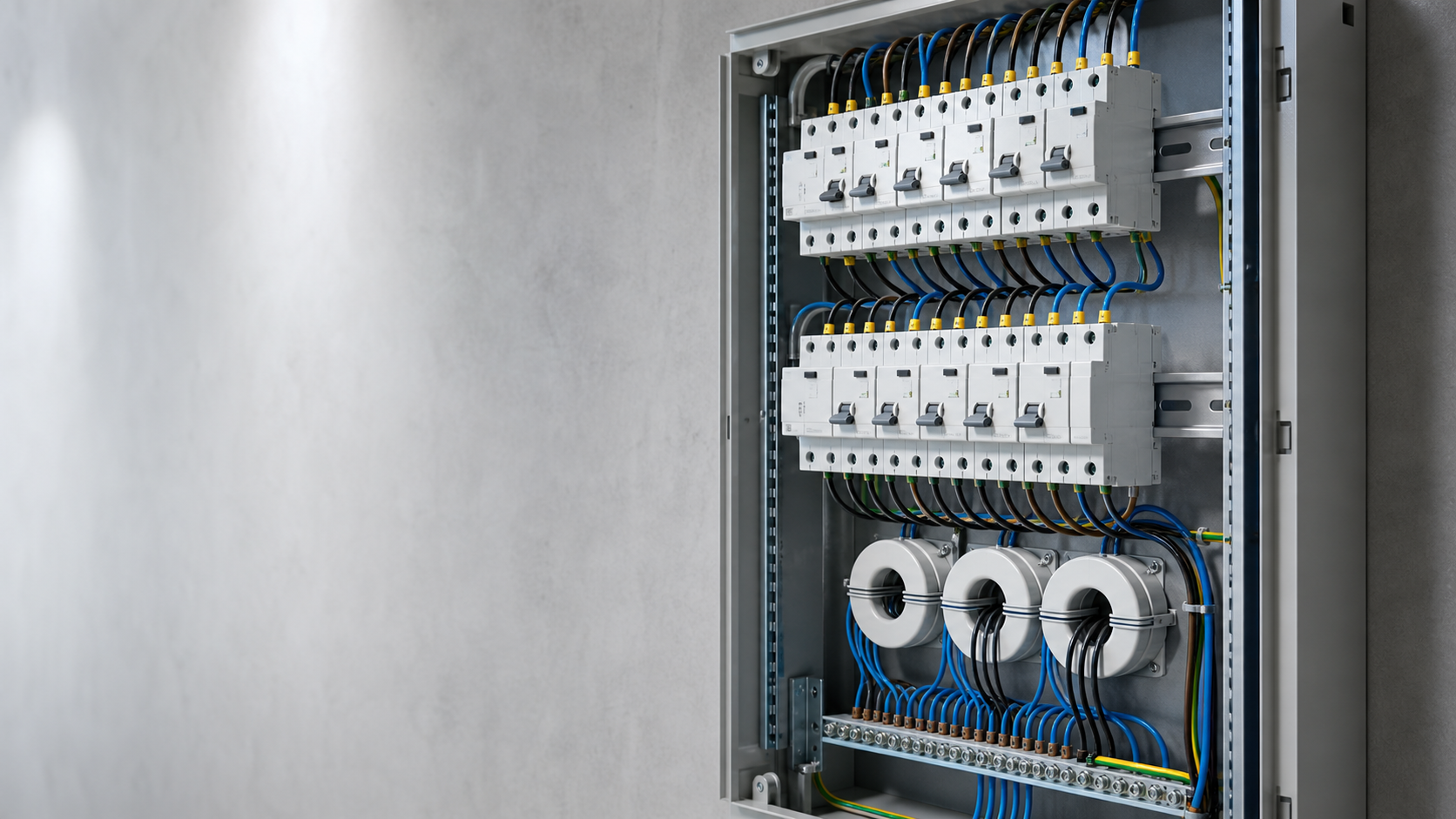
A Type B device carries two independent detection paths. The first is the familiar zero-sequence current transformer with a high-permeability core, which handles sinusoidal and pulsating residual currents passively and is the only sensing element in an AC or Type A device. The second is an actively driven magnetic modulator: an oscillator sweeps a second core through its magnetisation curve, and any DC flux offset produced by a direct residual current makes the positive and negative halves of that sweep asymmetric. Electronics measure the asymmetry and convert it into a direct-current reading down to a few milliamperes.
Because the modulator needs an oscillator and a comparator, a Type B device is electronically assisted rather than purely electromechanical. The AC detection path, however, remains passive, so the loss of the auxiliary supply does not remove basic residual-current protection. This split architecture is why a Type B device is described as all-current-sensitive: it covers sinusoidal, pulsating, mixed-frequency and smooth direct residual currents in one enclosure.
3. The 6 mA smooth-DC threshold and why it matters
The figure that dominates PV residual-current design is 6 mA of smooth DC. It is the level at which a direct residual current begins to bias the magnetic core of a conventional residual-current transformer far enough to reduce its sensitivity to the AC fault current it is supposed to detect. Inverter product standards therefore require that a transformerless unit either limits its own DC residual contribution below that value or disconnects, and RCD product standards use the same order of magnitude when defining direct-current immunity and tripping behaviour.
The practical consequence is a design rule rather than a number to memorise: if the steady DC component at the point of installation can approach 6 mA, the protective device on that circuit must be one that measures direct current instead of one that merely tolerates it. That is a Type B or otherwise all-current-sensitive device.
4. Type B versus Type A and AC on a PV inverter circuit
An AC-only device responds to sinusoidal residual current alone. A Type A device adds pulsating direct residual current, which covers most single-phase electronic loads but stops short of a steady direct component. A Type F device extends the Type A envelope into mixed frequencies for single-phase drive circuits and tolerates a small superimposed DC offset. Only Type B measures pure smooth DC and keeps its stated sensitivity while doing so.
AC type: sinusoidal residual current only — not suitable downstream of a transformerless inverter.
Type A: sinusoidal plus pulsating DC — blinded progressively by a smooth DC offset.
Type F: Type A envelope plus mixed frequencies and a limited DC offset — aimed at drive circuits.
Type B: adds true smooth DC measurement and retains sensitivity — the correct class for a transformerless PV AC circuit.
5. Inverter internal monitoring versus an external Type B device
Most modern transformerless inverters contain a residual-current monitor that watches the AC output and the DC input and disconnects the unit if the residual current, including its direct component, exceeds the limits set by the inverter product standard. That function is often described as Type B equivalent, and it genuinely covers the inverter itself. What it does not cover is the rest of the assembly: the AC cabling downstream of the inverter terminals, the busbar, the auxiliary circuits and any socket outlets or maintenance points inside the board.
The two functions therefore have different protection zones. The internal monitor protects the conversion stage; an external device in the AC board protects the wiring and the people working on it. Where the inverter documentation explicitly declares an integrated all-current-sensitive function and the installation rules of the project accept it, the external device may be reduced to a Type A for the remaining circuits — but that decision must be recorded, not assumed.
6. Sizing and pole configuration for PV AC boards
Rated current follows the continuous AC output of the inverter with the usual margin for ambient temperature inside the enclosure, and the residual sensitivity follows the protective purpose: 30 mA where additional protection for persons is required, 100 mA or 300 mA where the objective is fire protection on a feeder. Pole count follows the topology — two poles for a single-phase inverter, four poles for a three-phase inverter with a distributed neutral, and three poles only where the neutral is genuinely absent.
Rated current at least the inverter continuous AC output, derated for board ambient temperature.
Residual sensitivity chosen for the protective objective, not copied from a domestic circuit.
Short-circuit withstand coordinated with the upstream overcurrent device on the same feeder.
Auxiliary supply and status contact wired so an internal electronics failure is visible to the monitoring system.
Enclosure rating and terminal capacity matched to the AC cable actually installed.
7. Commissioning and trip test
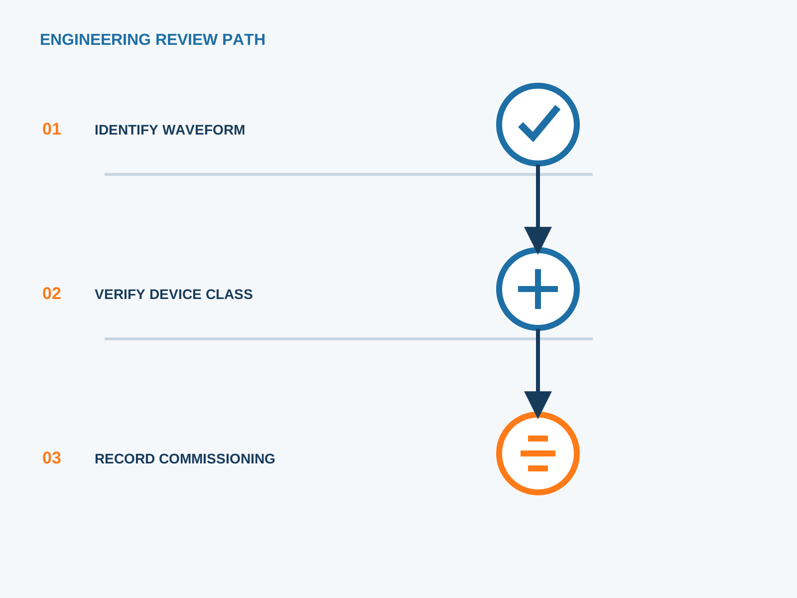
A test button proves the mechanical release, not the smooth DC path. Proper verification injects a calibrated residual current with a multi-function tester on each waveform the device claims to cover: sinusoidal at rated sensitivity, half-wave pulsating, and a smooth direct current. The measured tripping times are recorded against the manufacturer limits, and the test is repeated with the inverter running so that the natural leakage of the array is present in the measurement.
Record the ambient temperature, the array condition and the time of day. Leakage from parasitic capacitance varies with humidity and irradiance, so a commissioning record without those figures cannot be compared against a later maintenance test.
8. Summary checklist
Confirm from the inverter documentation whether the topology is transformerless and what residual current the unit declares.
Select an all-current-sensitive Type B device for the inverter AC circuit unless the project documentation formally accepts the integrated function.
Match rated current, pole count and short-circuit withstand to the board, not to a generic domestic template.
Verify sinusoidal, pulsating and smooth DC tripping at commissioning and file the readings.
Log leakage behaviour across a full day so nuisance trips can later be separated from real insulation faults.
NEUTRON supplies the DC protection assemblies and low-voltage switchgear that host these devices and can review a PV AC board arrangement against the protection scheme you have specified.
This is general application guidance. Confirm final ratings, trip settings, standards, inverter instructions and local installation requirements against approved project documentation and a qualified engineer's review.
Frequently asked questions
What makes PV inverter leakage different from ordinary grid AC leakage?
A transformerless inverter leaves the array galvanically connected to the grid, so the parasitic capacitance between cells and earthed frames carries a continuous displacement current that is modulated by the switching bridge. The resulting residual current contains high-frequency and steady direct components, whereas ordinary AC leakage is essentially sinusoidal at mains frequency.
Can a Type A RCD protect a transformerless PV inverter circuit?
Not reliably. A Type A device senses sinusoidal and pulsating residual current through a passive core. A smooth direct component biases that core and progressively reduces its sensitivity, so the device may fail to trip at its rated residual current when a real fault occurs. A Type B or otherwise all-current-sensitive device is required.
What is the smooth-DC detection threshold used in PV protection?
Six milliamperes of smooth direct current is the reference figure. It is the level at which a steady direct residual current starts to impair a conventional residual-current transformer, so inverter and RCD standards use that order of magnitude when defining direct-current behaviour.
Is an external Type B RCD still needed if the inverter monitors residual current?
The internal monitor protects the conversion stage only. Cabling, busbars, auxiliary circuits and maintenance points downstream of the inverter terminals sit outside its detection zone, so an external device is normally still required. Reducing it to a Type A is only acceptable when the inverter declares an integrated all-current-sensitive function and the project documentation accepts that arrangement.
Bring the protection inputs to the first review.
{ "@context": "https://schema.org", "@type": "Article", "headline": "Type B RCD Smooth DC Detection in PV Inverter Systems", "description": "Why transformerless PV inverters produce smooth DC leakage, how a Type B RCD detects it, and how to size, install and trip-test the device on a PV AC board.", "author": { "@type": "Organization", "name": "NEUTRON LLC" }, "publisher": { "@type": "Organization", "name": "NEUTRON LLC", "logo": { "@type": "ImageObject", "url": "https://www.neutronele.com/logo.png" } }, "datePublished": "2026-09-03", "dateModified": "2026-09-03", "mainEntityOfPage": "https://www.neutronele.com/insights/type-b-rcd-smooth-dc-detection-pv-inverters", "image": "https://www.neutronele.com/insights/img/type-b-rcd-smooth-dc-detection-pv-inverters-hero.jpg", "articleSection": "Electrical Protection", "keywords": "Type B RCD PV inverter, smooth DC residual current, all-current-sensitive RCD, transformerless inverter leakage, IEC 62423, 6mA DC", "inLanguage": "en" }
Discuss a project requirementContinue learning
Explore related technical guidance in Electrical Protection.

Published from the approved period 10 source package; technical claims and source wording are retained for review.