
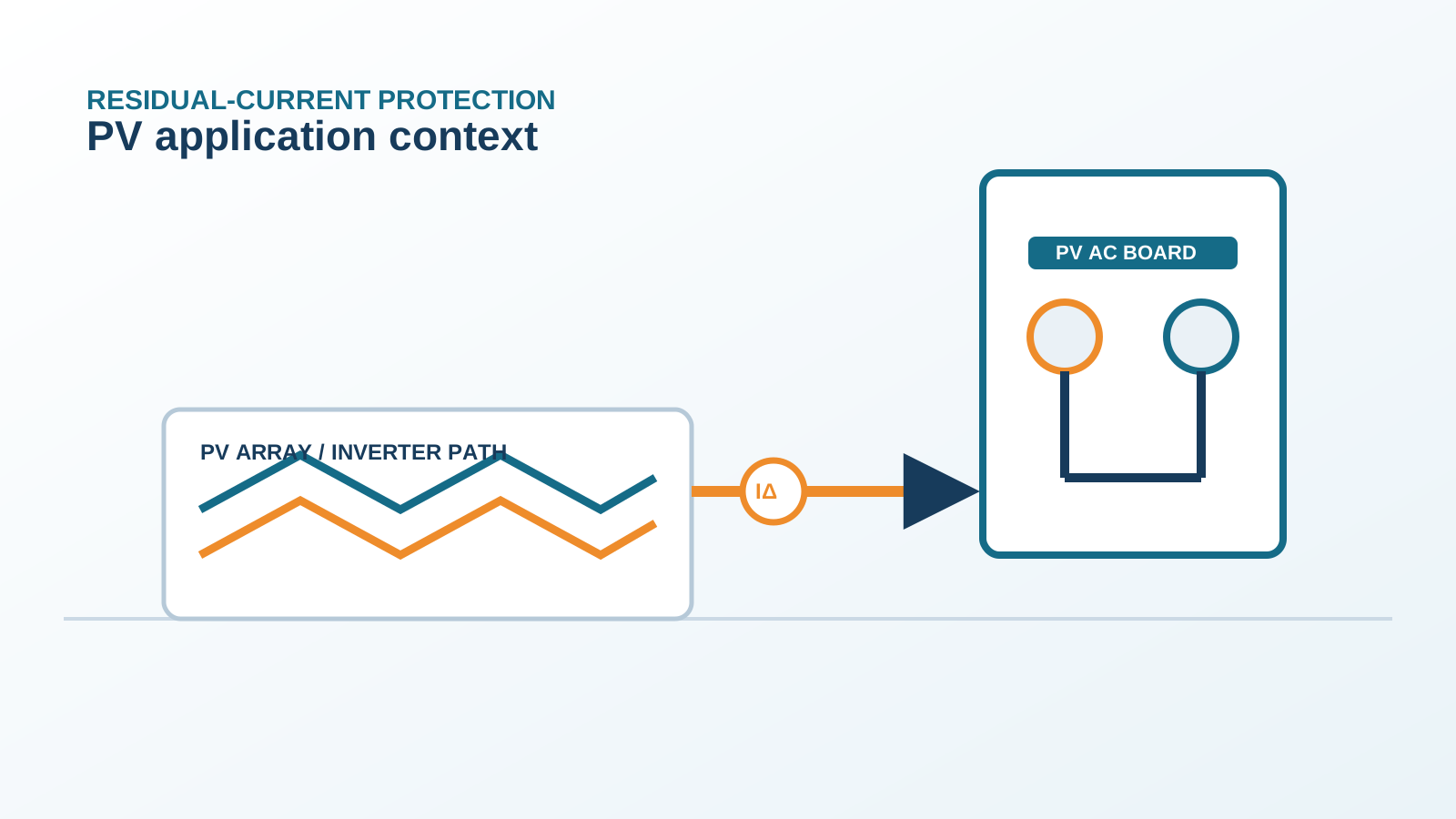
1. What an inverter-integrated RCM does
A residual-current monitor inside a transformerless inverter measures the vector sum of the currents crossing the boundary of the conversion stage. In most implementations a wideband sensor encircles the AC output conductors while the control electronics also evaluate the DC input side, so the monitor sees any current that leaves the converter by a path other than the intended conductors — through module parasitic capacitance, through degraded DC cable insulation, or through a genuine earth fault. The measurement covers the sinusoidal, mixed-frequency and steady direct components together.
The output is not merely an alarm. When a defined limit is exceeded the inverter opens its grid relay and stops exporting, which makes the monitor a protective function with a disconnection action rather than a telemetry channel. Most units also record the event, so the residual-current history is available for later analysis.
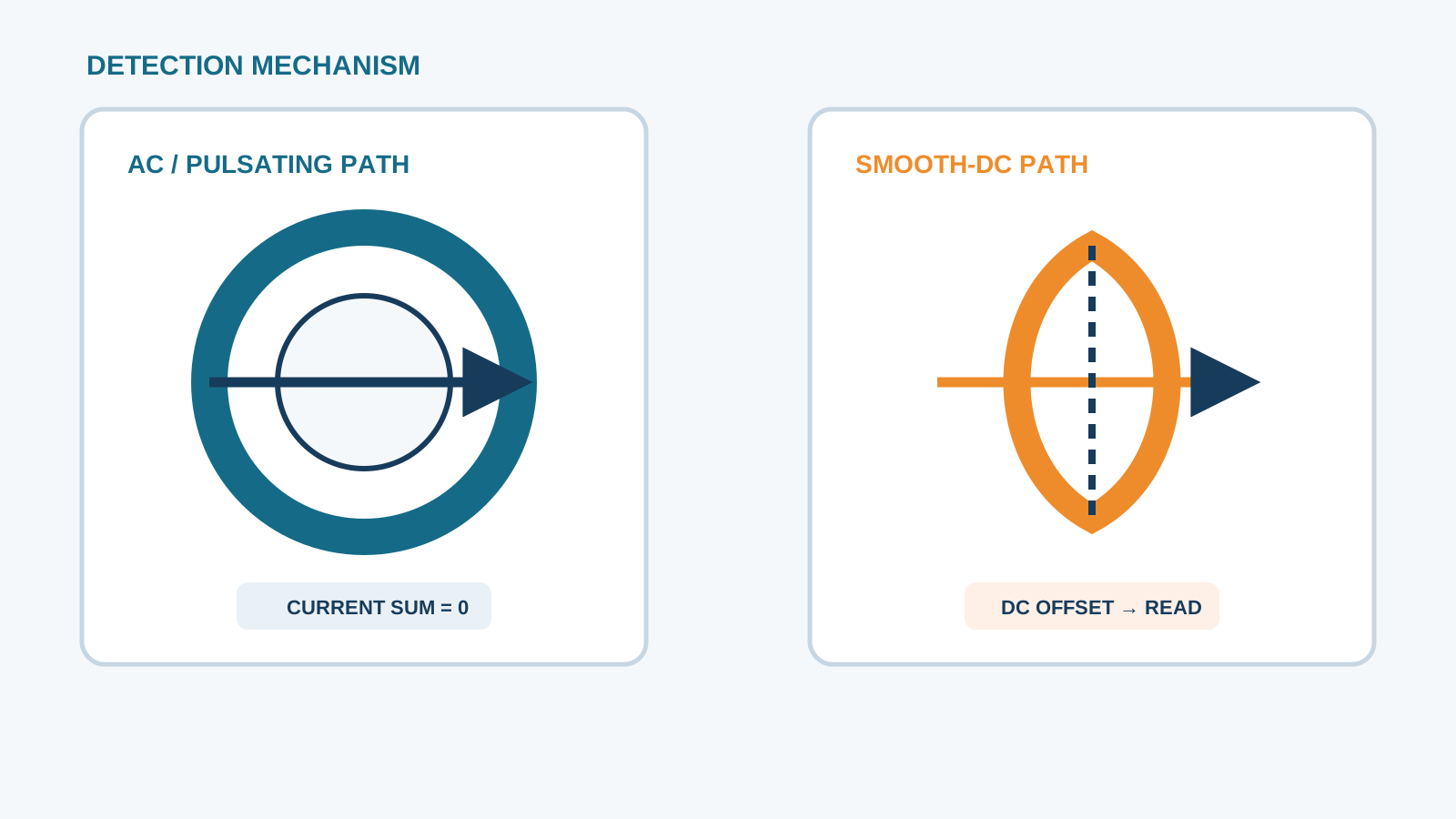
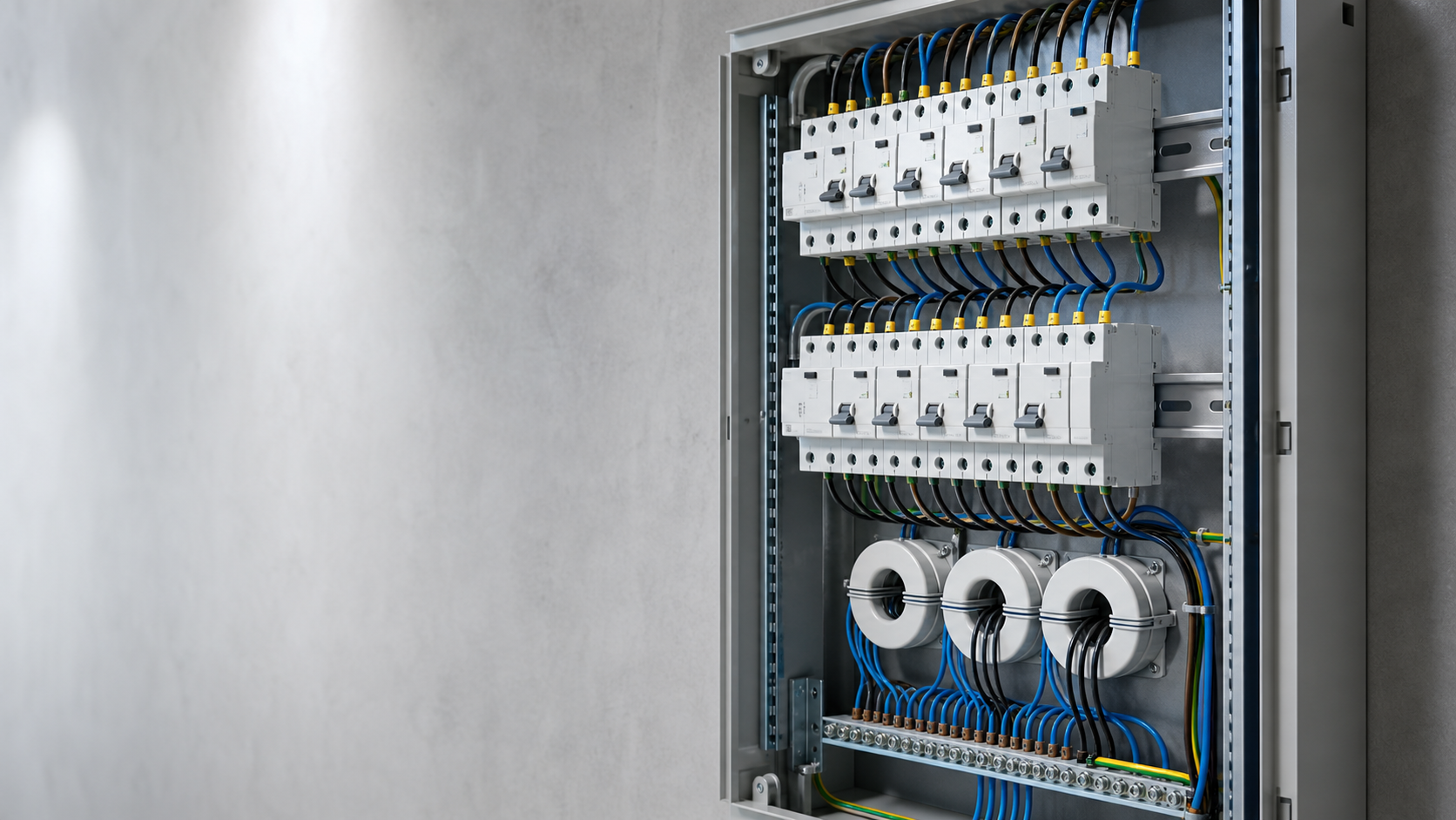
Technical diagram shown at a readable responsive scale.
2. Why it is considered Type B equivalent
The equivalence claim rests on the physics of the measurement rather than on a certificate. A Type B residual-current device is distinguished from a Type A by its ability to measure a smooth direct residual current instead of being biased by it. An inverter monitor built around a wideband sensor and digital evaluation shares that ability: it resolves the steady direct component down to a few milliamperes and does not lose sensitivity to the AC component while doing so.
The wording matters, though. Equivalent is not the same as certified to the residual-current device product standards. The monitor is assessed as part of the inverter under the converter safety standard, not as a stand-alone protective device under IEC 61008, IEC 61009 or IEC 62423. Where an installation rule calls for a device of a stated type, the designer must check whether an integrated function is accepted in that jurisdiction rather than assume the equivalence transfers.
3. Detection of smooth DC and the sudden-change limits
IEC 62109-2 sets two families of limit for the integrated monitor. The first is a continuous limit on the steady residual current the unit may run with, commonly implemented at the order of 6 mA per rated output ampere for the direct component, which keeps the inverter contribution below the level that would bias a conventional core downstream. The second is a set of sudden-change limits: defined step increases in residual current must cause disconnection within a specified time, because a step is the signature of a fault appearing rather than of leakage drifting with weather.
Continuous direct-current limit: keeps the standing contribution small enough not to blind downstream protection.
Sudden-change limits: force disconnection on step increases, which is how a new earth fault presents itself.
Combined effect: slow weather-driven drift is tolerated while abrupt insulation failure causes a trip.
Practical consequence: the monitor discriminates better than a fixed threshold alone could.
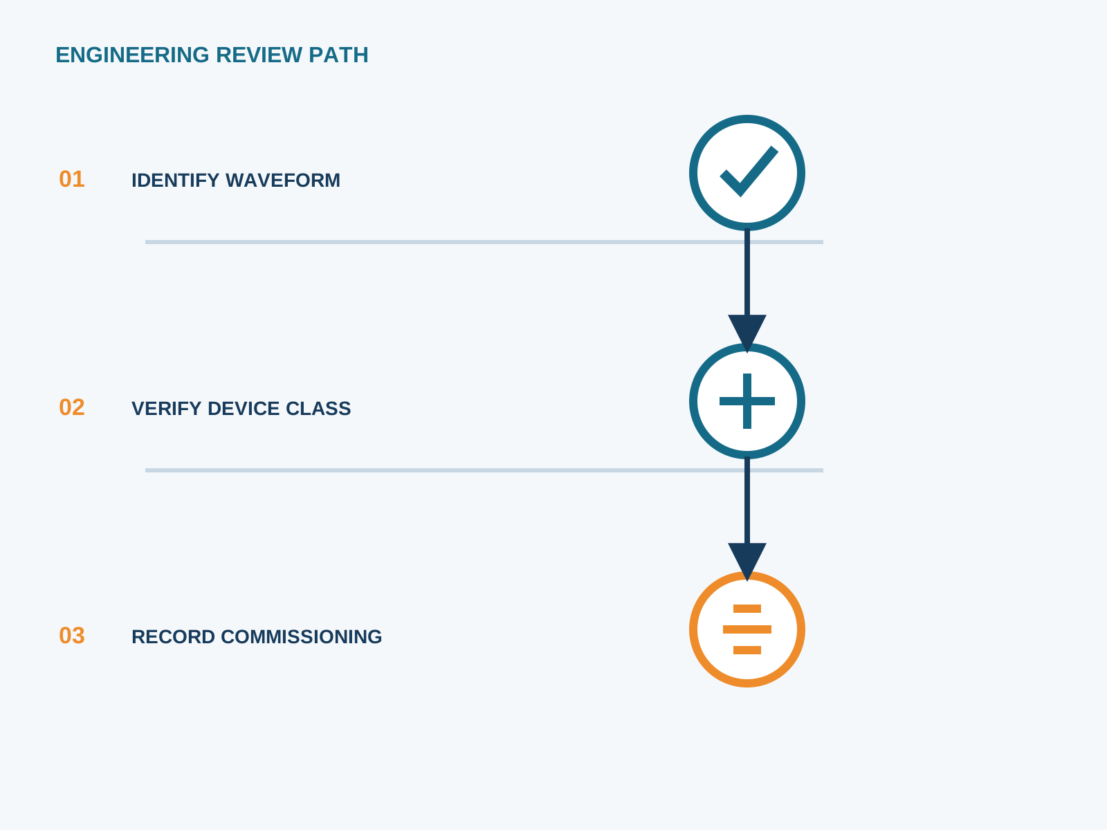
4. Inverter disconnection versus external RCD tripping
The two actions are not interchangeable. When the internal monitor acts, the inverter stops exporting and opens its grid relay, but the AC circuit remains energised from the grid side and the DC side of the array remains live in daylight. When an external residual-current device in the AC board acts, the AC circuit is disconnected from the grid, which removes the supply to the cabling and to anything else on that circuit, while the array again remains live.
Which acts first depends on the fault location and the settings. A fault inside the conversion stage or on the DC side is normally seen only by the internal monitor. A fault on the AC cabling downstream of the inverter terminals is seen by the external device and may not register on the internal monitor at all. That asymmetry is the whole argument for keeping both.
5. Does it remove the need for an external Type B device?
For the conversion stage, the integrated monitor is a genuine protective function and generally sufficient. For the installation as a whole it is not, because the AC cabling, the board busbar, the auxiliary circuits and any maintenance socket outlets sit outside its detection zone and are exactly the parts a person is most likely to touch.
Where the project documentation and the applicable installation rules accept a declared integrated all-current-sensitive function, the external device on that circuit may sometimes be reduced from Type B to Type A, on the reasoning that the inverter guarantees the direct component stays below the biasing level. That reduction is a documented engineering decision requiring the manufacturer declaration on file — not a default. Where several inverters share a board, the accumulated direct component at the upstream device must be assessed before any such reduction is considered.
6. Limitations: one point, not the whole board
Detection zone limited to the converter boundary — AC cabling and busbars downstream are not covered.
Auxiliary and control circuits fed from the same board are outside the measurement.
A fault that appears only when the inverter is off-line at night cannot be detected by a monitor inside a stopped unit.
The disconnection removes export but does not isolate the AC circuit from the grid.
Threshold behaviour is fixed by the manufacturer and cannot be coordinated with upstream protection the way a selectable external device can.
Assessment is under the converter safety standard, not under the residual-current device product standards.
7. Commissioning and fault logging
Commissioning the integrated function is mostly a documentation and data exercise. Confirm from the inverter interface that the monitor is active and read the standing residual current at full export, then repeat the reading in the early morning when module surfaces are damp and the figure is highest. Record both values with irradiance, ambient temperature and humidity so a later maintenance reading can be compared meaningfully.
Configure the plant monitoring system to retain the residual-current history and the disconnection events rather than only the energy data. A slow upward drift in standing residual current over months is the earliest available indication of insulation degradation in the DC field, and it is only visible if the log is kept.
8. Combined scheme: internal plus external
The arrangement that works in practice treats the two functions as covering different zones. The integrated monitor protects the conversion stage and provides the residual-current trend data. An external all-current-sensitive device in the AC board protects the cabling, the busbar and the people working on the assembly, with its sensitivity chosen from the protective objective and a documented margin above the measured standing leakage. The two are then coordinated so that a DC-side fault stops the inverter without dropping the whole board, while an AC-side fault opens the board device.
NEUTRON supplies the DC protection assemblies and low-voltage switchgear in which the external device sits, and can review a proposed internal-plus-external arrangement against the inverter declaration you hold.
This is general application guidance. Confirm final ratings, trip settings, standards, inverter instructions and local installation requirements against approved project documentation and a qualified engineer's review.
Frequently asked questions
Is the inverter RCM a replacement for an external Type B RCD?
For the conversion stage it is a genuine protective function; for the installation it is not. The AC cabling, board busbar, auxiliary circuits and maintenance points lie outside its detection zone. Reducing the external device is only acceptable when the manufacturer declares an integrated all-current-sensitive function and the project documentation and installation rules accept it.
What standard covers the inverter residual-current monitor?
IEC 62109-2, the safety standard for power converters used in photovoltaic systems. It sets both a continuous limit on the steady direct residual current the unit may run with and a set of sudden-change limits that force disconnection when the residual current steps upward.
What trips first, the inverter or the external RCD?
It depends on where the fault is. A fault inside the conversion stage or on the DC side is normally seen only by the internal monitor, which stops export. A fault on the AC cabling downstream of the inverter terminals is seen by the external device and may not register internally at all.
Can the inverter RCM miss leakage elsewhere on the board?
Yes. It measures only what crosses the converter boundary, so leakage on the board busbar, on auxiliary circuits or on other outgoing ways is invisible to it. A fault that appears while the inverter is off-line at night is also outside its reach.
Bring the protection inputs to the first review.
{ "@context": "https://schema.org", "@type": "Article", "headline": "Inverter Residual-Current Monitor as a Type B Equivalent", "description": "What an inverter-integrated residual-current monitor does, why it is called Type B equivalent, what it cannot cover, and how to pair it with an external device.", "author": { "@type": "Organization", "name": "NEUTRON LLC" }, "publisher": { "@type": "Organization", "name": "NEUTRON LLC", "logo": { "@type": "ImageObject", "url": "https://www.neutronele.com/logo.png" } }, "datePublished": "2026-09-03", "dateModified": "2026-09-03", "mainEntityOfPage": "https://www.neutronele.com/insights/inverter-internal-residual-current-monitor-type-b-equivalent", "image": "https://www.neutronele.com/insights/img/inverter-internal-residual-current-monitor-type-b-equivalent-hero.jpg", "articleSection": "Electrical Protection", "keywords": "inverter internal residual current monitor, RCM, 6mA DC monitor, IEC 62109-2, Type B equivalent, PV safety, trip on fault", "inLanguage": "en" }
Discuss a project requirementContinue learning
Explore related technical guidance in Electrical Protection.

Published from the approved period 10 source package; technical claims and source wording are retained for review.