
1. What Type F adds over Type A
A Type A device is verified against sinusoidal residual current and half-wave pulsating direct residual current. A Type F device keeps that whole envelope and adds two things: verification against a composite residual current containing several frequency components simultaneously, and a defined tolerance to a superimposed smooth direct current of a small magnitude, commonly quoted as 10 mA in the class definition. It also has a specified behaviour at higher test frequencies than Type A, reflecting the loads it targets.
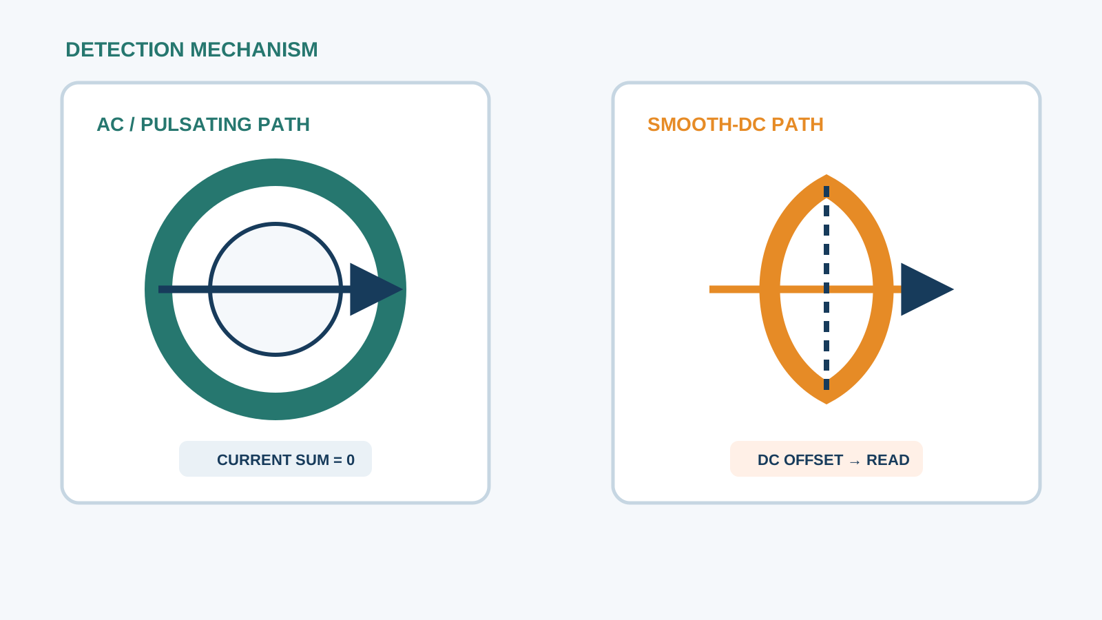
The important nuance is that the direct-current figure is a tolerance, not a detection capability. A Type F device is designed to keep working correctly while a small steady direct residual current is present; it does not measure that current and will not trip on it. That single distinction determines every application decision that follows.
Technical diagram shown at a readable responsive scale.
2. PV pumping and converter leakage character
In a solar pumping installation, the converter output is a train of steep voltage edges rather than a sinusoid. The motor cable and the motor windings both present capacitance to earth, and each voltage edge drives a displacement current through that capacitance. The result is a common-mode leakage current concentrated at the converter switching frequency and its harmonics, with amplitude proportional to cable length, edge steepness and switching frequency. On a long run to a borehole pump, that leakage can be tens of milliamperes even with perfectly healthy insulation.
Superimposed on this is the fundamental output frequency of the converter, which varies as the pump speed follows available irradiance. The residual current therefore has a moving low-frequency component as well as a fixed high-frequency cluster, which is exactly the composite waveform the Type F class was defined to handle.
3. Mixed-frequency residual current in practice
Treating this leakage as a single number is the usual mistake. The total measured with a wideband clamp is the sum of components that behave differently and that a protective device weights differently, because sensitivity falls as frequency rises.
Converter output fundamental, variable with pump speed: fully within the sensitivity band of any class.
Low-order harmonics of the output: near-full sensitivity, contributing directly to the tripping quantity.
Switching-frequency cluster and sidebands: attenuated by the rising threshold of every class, often the largest raw contribution to a clamp reading.
Steady direct component from a transformerless supply stage: not detected by Type A or Type F at all, only tolerated.
4. Type F or Type B for a pump load
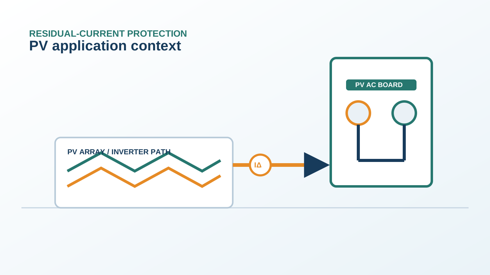
The decision follows the topology of the supply, not the presence of the pump. Where the converter is fed from a grid AC supply, or from a PV system through a conversion stage that provides galvanic separation, the residual current is mixed-frequency without a significant steady direct component and a Type F device is the proportionate, standard-conforming choice. Where the converter is fed directly from a photovoltaic array through a transformerless stage — as most dedicated solar pump controllers are — a steady direct component is present by construction, and Type F is not sufficient because it cannot measure it.
In that second case the correct class is Type B, or Type B+ where measurement shows substantial residual energy above the declared band of a standard Type B device. A useful discipline is to ask a single question of the drawing: is there a galvanic barrier between the array and the protected circuit? If the answer is no, the answer to the device question is Type B or above.
5. Sizing the pump AC circuit
Rated current from the converter input current, not the motor nameplate, derated for cabinet ambient temperature.
Residual sensitivity chosen with a documented margin above the measured standing converter leakage — commonly 300 mA on a long-cable borehole feeder rather than 30 mA.
Short time delay on the feeder device so that switching transients and pump start do not cause release.
Thirty milliampere instantaneous protection reserved for accessible circuits such as maintenance socket outlets in the pump house.
Pole count matched to the converter supply — two poles single-phase, four poles three-phase with a distributed neutral.
Enclosure rating suited to a pump house or field cabinet, with terminal capacity for the installed cable.
6. Earthing of the converter and motor
Earthing practice determines how much of the converter leakage ever reaches the protective device as an unwanted residual current. A shielded motor cable with the shield bonded over its full circumference at both the converter and the motor gives the common-mode current a low-impedance return path close to the conductors that generated it, so it circulates locally instead of wandering through the installation earthing system. A pigtail connection at one end defeats most of that benefit.
The converter protective earth must be short, direct and generously sized, and the motor frame must be bonded to the same reference. Where the pump is submerged in a borehole, the earthing of the wellhead structure and the riser becomes part of the electrical system and needs the same attention. Disconnecting the converter internal filter to reduce a clamp reading is not a remedy: it moves emission from the filter into the earthing system and must be evaluated rather than assumed to help.
7. Field commissioning
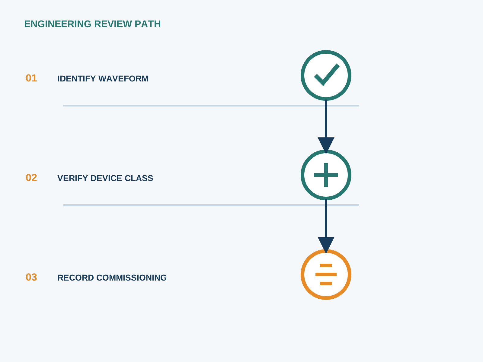
Measure standing residual current with a wideband clamp around all live conductors of the converter supply, at low pump speed and at full speed.
Verify the device by calibrated injection on each declared waveform and record the tripping times.
Check the shield termination at both cable ends physically, since a pigtail is the most common defect found.
Measure the residual spectrum with a probe and oscilloscope where a trip cannot be explained by the total figure alone.
Confirm with a true-DC clamp whether a steady direct component exists; if it does, the device class must be reconsidered.
File all readings with irradiance, ambient temperature and pump duty as the maintenance baseline.
8. When to step up to Type B+
Step up when the residual spectrum shows substantial energy above the declared detection band of a standard Type B device — typically the case with a high switching frequency, a long motor cable, or both. The trigger for that decision should be a measurement rather than a precaution, because a B+ device is wider and costs more per pole, and specifying it on a circuit that does not need it adds no protection.
The decision is per circuit. A borehole pump feeder may justify Type B+ while other outgoing ways on the same board are correctly served by Type B, and the accessible socket circuits in the pump house are served by 30 mA instantaneous devices. NEUTRON supplies the DC protection assemblies and low-voltage switchgear that host these devices and can review a pumping installation against the classes you have specified.
This is general application guidance. Confirm final ratings, trip settings, standards, inverter instructions and local installation requirements against approved project documentation and a qualified engineer's review.
Frequently asked questions
Is a Type F device enough for a PV pump?
Only when the converter supply has a galvanic barrier between the array and the protected circuit. Type F handles the mixed-frequency leakage of a converter and tolerates a small superimposed direct current, but it does not measure a steady direct component. A dedicated solar pump controller fed directly from the array produces that component by construction, so Type B or above is required.
Type F or Type B for a frequency-converter load?
Ask whether a steady direct residual current can occur. With a transformerless supply stage the answer is yes and the device must be Type B, or Type B+ where measurement shows substantial energy above the standard Type B band. With a galvanically separated or grid-fed converter, Type F is the proportionate choice.
What frequencies must a Type F device cover?
Type F is verified against a composite residual current containing several frequency components at once, with specified behaviour at higher test frequencies than Type A, and it tolerates a small superimposed smooth direct current commonly quoted as 10 mA. Coverage far above that band belongs to the Type B+ class.
Does the pump motor need its own residual-current device?
Normally the protective device sits on the converter supply rather than between the converter and the motor, because the converter output is not a sinusoidal supply and a device there would respond to the switching leakage of the cable. Accessible circuits in the pump house, such as maintenance socket outlets, do need their own 30 mA instantaneous protection.
Bring the protection inputs to the first review.
{ "@context": "https://schema.org", "@type": "Article", "headline": "Type F RCD for PV Pumping and Frequency-Converter Loads", "description": "What the Type F residual-current class adds over Type A, how PV pump converter leakage behaves, and when a pump circuit needs Type B or Type B+ instead.", "author": { "@type": "Organization", "name": "NEUTRON LLC" }, "publisher": { "@type": "Organization", "name": "NEUTRON LLC", "logo": { "@type": "ImageObject", "url": "https://www.neutronele.com/logo.png" } }, "datePublished": "2026-09-03", "dateModified": "2026-09-03", "mainEntityOfPage": "https://www.neutronele.com/insights/type-f-rcd-frequency-converters-pv-pump", "image": "https://www.neutronele.com/insights/img/type-f-rcd-frequency-converters-pv-pump-hero.jpg", "articleSection": "Electrical Protection", "keywords": "Type F RCD PV pump, frequency converter, multi-frequency residual current, IEC 62423 Type F, PV water pump, VFD", "inLanguage": "en" }
Discuss a project requirementContinue learning
Explore related technical guidance in Electrical Protection.

Published from the approved period 10 source package; technical claims and source wording are retained for review.