
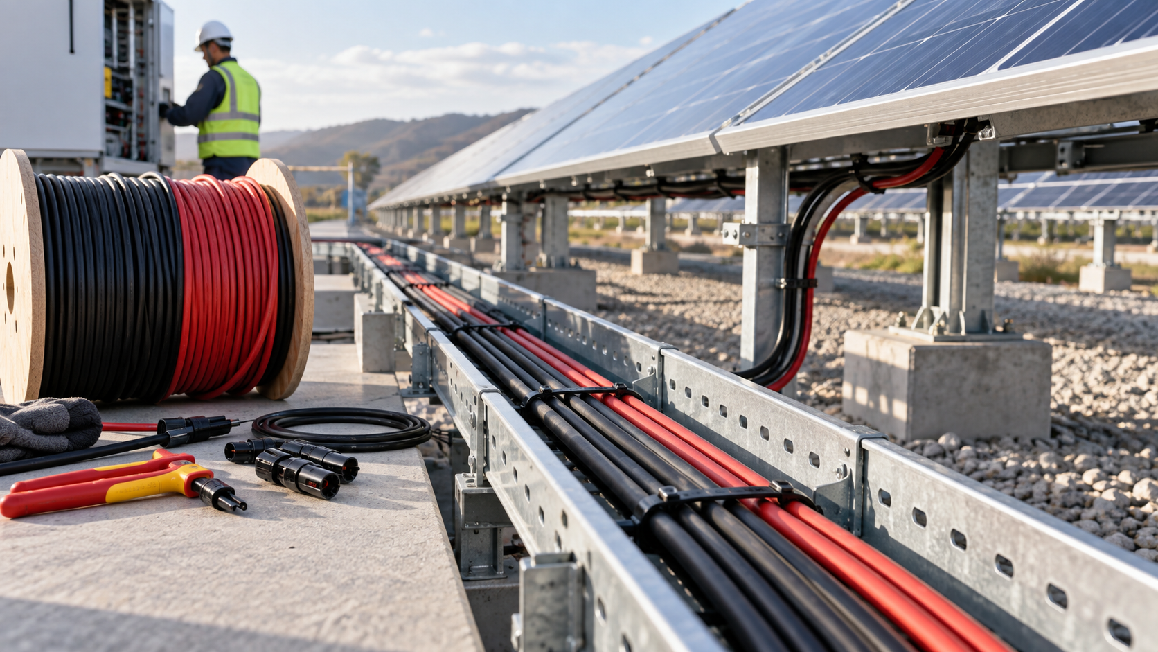
Why DC cable sizing is not optional
Undersized DC conductors in a photovoltaic array create heat, voltage loss and, in the worst case, a fire path. The DC side carries high continuous current at voltages that can exceed 1000 V, so the cable must be selected for the actual operating conditions rather than a nominal guess. NEUTRON specifies DC control and protection wiring against measured string data before assembly.
Correct sizing protects the investment on both ends: it preserves yield by limiting drop, and it keeps the combiner box and disconnect path within their temperature ratings.
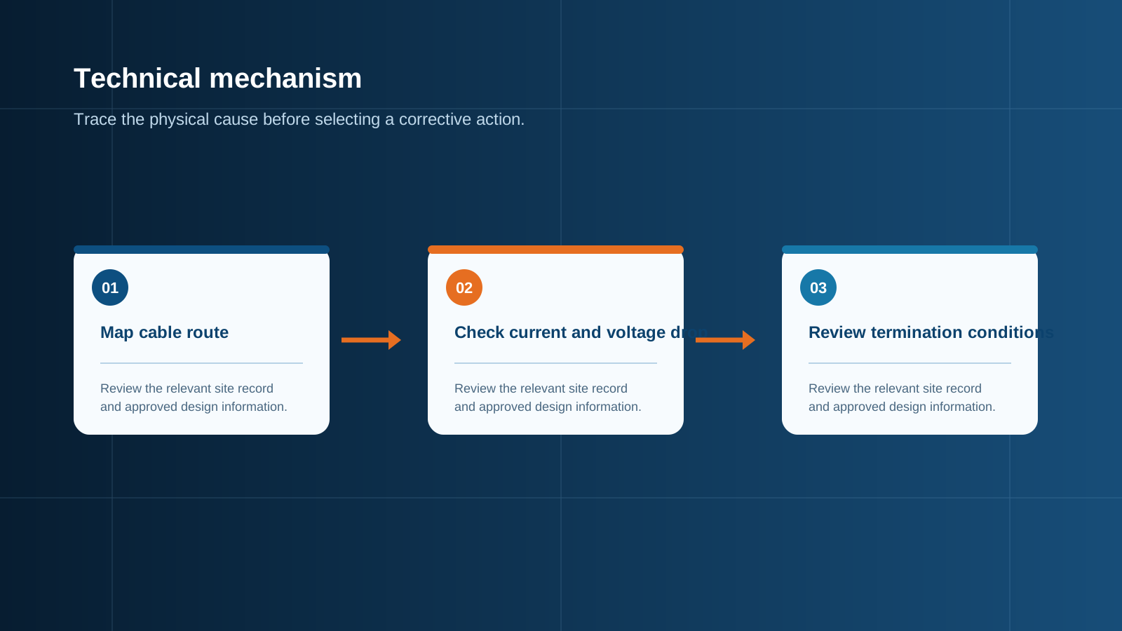
Technical diagram shown at a readable responsive scale.
Conductor cross-section by current
The first input is the string short-circuit current (Isc). Conductor cross-section is chosen so the cable carries the fused current with an acceptable temperature rise. As a practical rule, 2.5 mm² copper serves light strings, 4 mm² covers most residential strings, 6 mm² suits longer runs, and 10 mm² is common for high-current or bundled routes.
- 2.5 mm² — small strings and short indoor runs inside the enclosure.
- 4 mm² — standard residential PV string conductor.
- 6 mm² — longer array runs or higher Isc modules.
- 10 mm² — high-current strings and combiner output bus links.
The 2.5 / 4 / 6 / 10 mm² chart
A quick-reference chart maps cross-section to a safe continuous current under typical PV installation conditions. These figures assume single-core copper with standard PVC or PV-rated insulation at a controlled ambient. Always apply the project-specific derating before final selection.
- 2.5 mm² — up to ~20 A continuous.
- 4 mm² — up to ~30 A continuous.
- 6 mm² — up to ~40 A continuous.
- 10 mm² — up to ~60 A continuous.
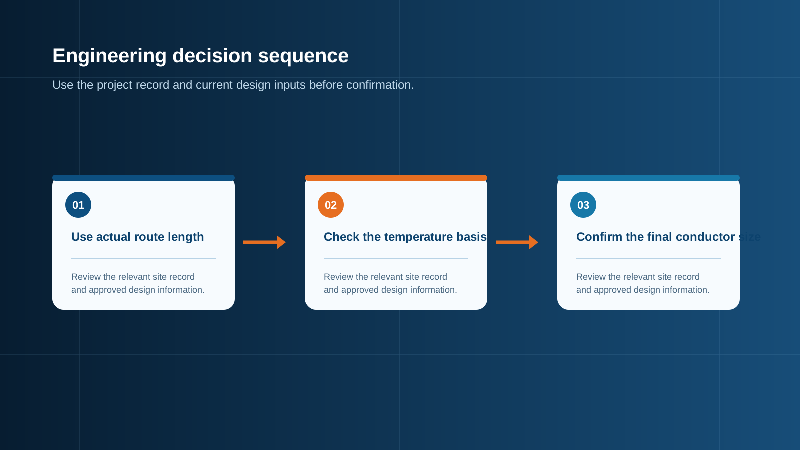
Technical diagram shown at a readable responsive scale.
Calculating voltage drop
Voltage drop is found from the conductor resistance, the current and the run length: drop equals current multiplied by resistance per metre and doubled for the return path. Keep the loss under roughly 3% on the DC side so the inverter sees near nameplate voltage. A long run on a thin cable silently steals output every sunny day.
- Use the full loop length, not just the one-way distance.
- Step up cross-section before stepping up breaker size.
AWG-to-metric mistakes to avoid
Many installers think in AWG while PV cable is stamped in mm². A 10 AWG conductor is about 5.3 mm², not the 6 mm² some assume, and 12 AWG is near 3.3 mm². Mixing the two systems leads to cables that look adequate but fail the current test.
- 10 AWG ≈ 5.3 mm², not 6 mm².
- 12 AWG ≈ 3.3 mm², not 4 mm².
Temperature and bundling derating
Cables routed in conduit, in a bundle, or exposed to roof heat lose current capacity. The same 4 mm² that is fine in open air may need to step to 6 mm² when packed with other conductors. NEUTRON accounts for enclosure temperature when laying out combiner box internal wiring.
Connectors and termination
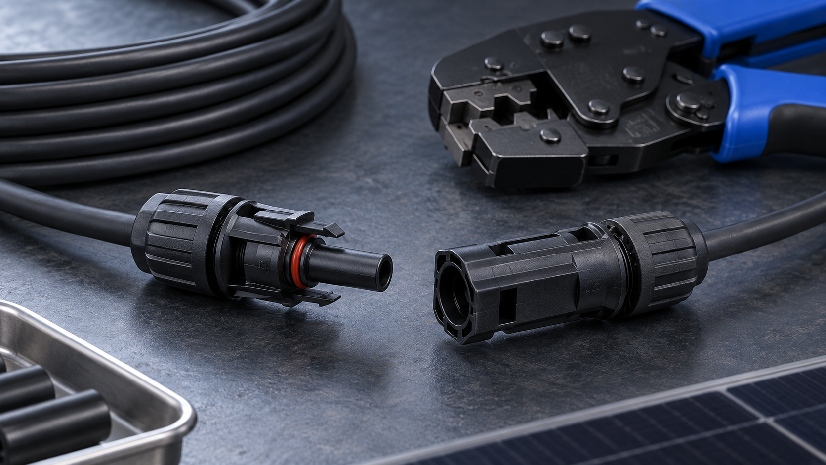
The cable is only as good as its termination. MC4 connectors must be the correct pin rating and crimped with the proper tool, and torque at busbar terminals must be verified. A loose termination creates the same heat risk as an undersized conductor.
- Match connector family across the string.
- Verify crimp and torque at every termination.
Cable routing inside the combiner box
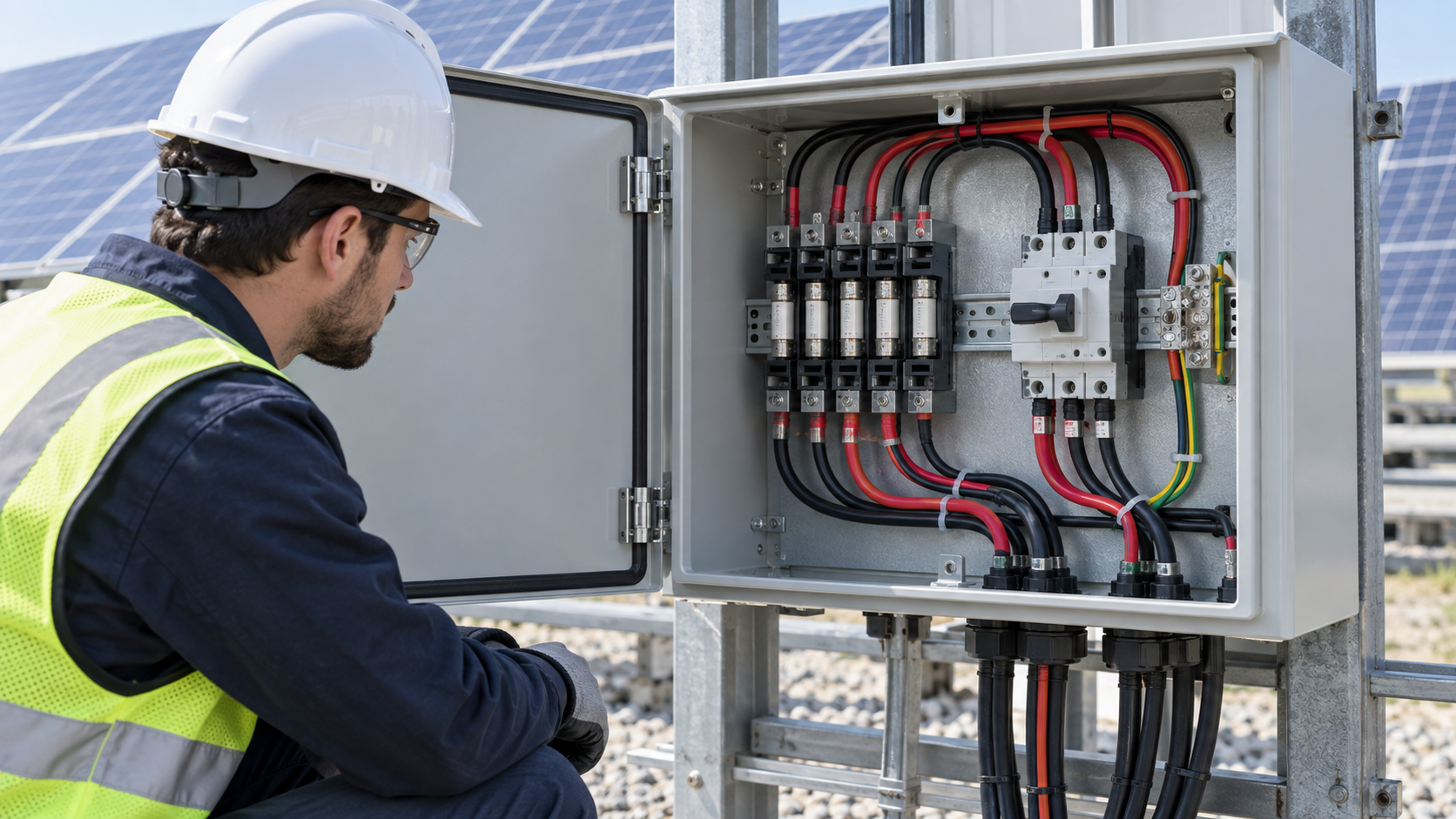
Inside the enclosure, conductors must be separated, supported and rated for the DC environment. NEUTRON routes each string to its gPV fuse and then to the busbar with clear spacing, keeping voltage drop and thermal rise inside the design envelope. Good internal routing is what turns a cable schedule into a reliable assembly.
This is general technical guidance. Confirm final ratings, protection coordination, installation and applicable local requirements against current standards, manufacturer documentation and the approved project design.
Frequently asked questions
What size DC cable for my array?
Start from the string Isc and the run length. Most residential strings use 4 mm² copper; longer or higher-current runs move to 6 mm², and combiner output links often use 10 mm². Confirm against the voltage-drop budget.
How do I calculate voltage drop?
Multiply the current by the conductor resistance per metre and by the full loop length, then compare the loss to about 3% of the string voltage. If it exceeds the budget, increase the cross-section.
6 mm² equals what AWG?
6 mm² is between 9 AWG and 10 AWG in area, closer to 9 AWG; it is not equal to 10 AWG (≈5.3 mm²). Always convert carefully when mixing metric and AWG systems.
Does cable size affect fuses?
Yes. The gPV fuse is sized to the string Isc (typically 1.25×Isc), while the cable must carry that fused current without overheating. The cable cross-section and the fuse rating must be coordinated, not chosen independently.
Discuss your PV requirement
Share the system voltage, string arrangement, inverter interface and installation environment. NEUTRON can review the equipment configuration around your project documentation.
Discuss a projectContinue learning
Explore related technical guidance in Electrical Protection.
Published from the approved Period 06 source package. Technical values and final design decisions must be verified against the current applicable standard, manufacturer documentation and approved project design.