
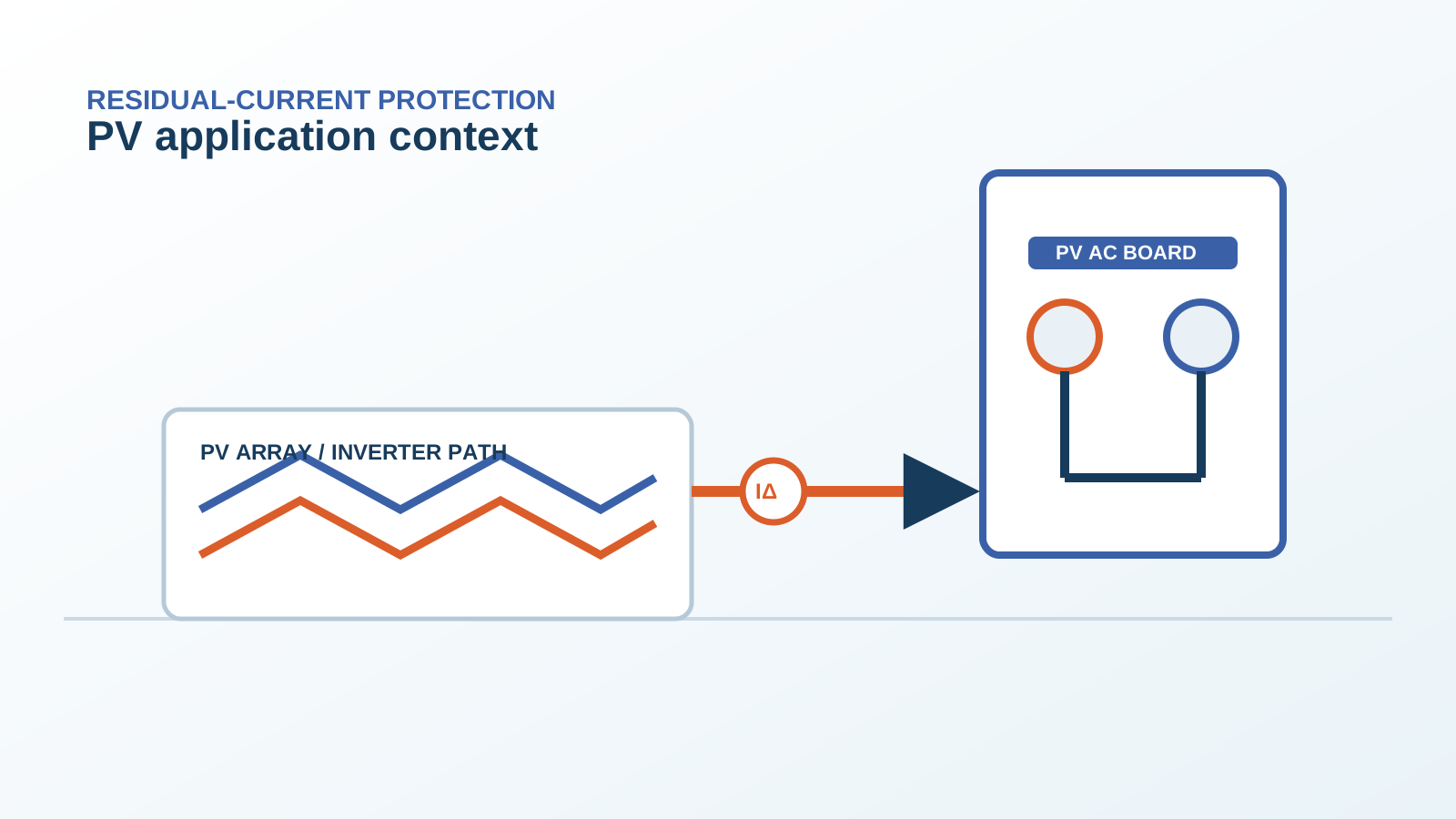
1. Where the 6 mA figure comes from
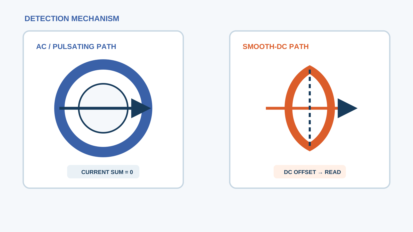
A conventional residual-current device senses through a toroidal core of high-permeability material operating in the narrow linear region of its magnetisation curve. A steady direct current in the primary conductors imposes a fixed magnetisation offset, moving the operating point towards the knee of that curve and reducing the incremental permeability available for detecting the AC residual current the device exists to find. Investigations into that interference established that a few milliamperes of direct current is enough to matter for a typical 30 mA device, and 6 mA became the practical dividing line adopted across the standards framework.
The figure therefore describes an instrument limitation, not a physiological one. Six milliamperes of direct current through a person is not the hazard; six milliamperes of direct current through the core of a protective device that is supposed to be watching for a much larger AC fault is. Once that is clear, everything else about PV residual-current design follows logically.
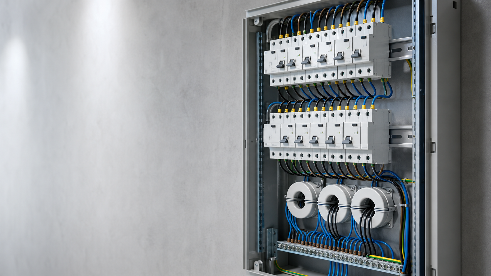
Technical diagram shown at a readable responsive scale.
2. Smooth versus pulsating direct current
The distinction between smooth and pulsating direct current is the single most misread point in this subject. A pulsating direct current is unidirectional but strongly varying — the half-wave rectified shape produced by a simple electronic load. Because it varies, it still induces a voltage in a sensing winding, which is why a Type A device can detect it. A smooth direct current is unidirectional and essentially constant, with only slight ripple. It induces nothing, and it is the shape a transformerless inverter contributes.
Sinusoidal AC residual current: detected by every class from AC upward.
Pulsating DC residual current: detected by Type A and above; strongly varying, so a passive core still responds.
Mixed-frequency residual current: within the declared envelope of Type F and above.
Smooth DC residual current: only measured by Type B and Type B+; invisible to a passive core and the cause of the bias effect.
3. The inverter internal monitor and the same figure
The inverter product standard for grid-connected equipment, IEC 62109-2, requires a transformerless unit to monitor its own residual current and to disconnect when defined limits are exceeded. Two of those limits are relevant here: a continuous limit on the steady direct residual current the unit may contribute, of the order of 6 mA per rated output ampere in common implementations, and a set of sudden-change limits that force disconnection when the residual current jumps by defined steps. The first limit is what keeps the inverter contribution from biasing downstream protection; the second is what makes the monitor a protective function rather than a telemetry point.
This is why inverter documentation frequently states that the internal monitor is Type B equivalent. The claim is reasonable for the conversion stage, because the monitor genuinely measures the direct component rather than merely tolerating it. It says nothing about the circuits outside the inverter enclosure.
4. An external RCD must also handle 6 mA of smooth DC
The inverter limits its own contribution, but the direct residual current that reaches a device in the AC board is the sum of the inverter contribution and everything the array and cabling add through insulation leakage and parasitic capacitance. In a plant with several inverters on a common board, those contributions accumulate at the upstream device even when each individual unit is well inside its own limit.
The consequence is a two-part rule. A device protecting the circuit of a single transformerless inverter must be able to measure smooth direct current, because the local contribution alone can approach the significant region. A device upstream of several inverters must be assessed against the accumulated total, and in practice that pushes it towards the same all-current-sensitive class, with a residual sensitivity chosen for fire protection rather than personal protection.
5. Measurement method on site
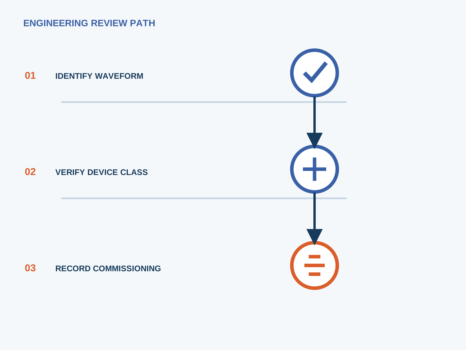
Measuring a few milliamperes of steady direct current in the presence of full load current requires the right instrument and the right technique.
Use a leakage clamp with true DC capability and a resolution of 0.1 mA or better; a standard AC clamp cannot do this.
Clamp around all live conductors of the circuit together, including the neutral where one exists, so the reading is the residual and not the load current.
Take readings with the inverter isolated, at part load and at full export, so the inverter contribution can be separated from the standing array leakage.
Record irradiance, ambient temperature, humidity and time of day alongside every reading.
Repeat in the early morning when module surfaces are damp, because that is when the highest figures normally appear.
6. Why an over-sensitive setting causes nuisance trips
It is tempting to answer a DC leakage concern by fitting the most sensitive device available. That usually makes the plant worse. A healthy PV array has an irreducible standing leakage from module parasitic capacitance that varies with irradiance, humidity and array size, and it is present whenever the inverter runs. Setting a residual threshold close to that standing figure guarantees trips that have nothing to do with a fault.
The correct approach is to measure the standing leakage across a full day, keep a clear margin between it and the tripping threshold, and choose the sensitivity from the protective objective — 30 mA where additional protection for persons is required, 100 mA or 300 mA on a feeder where the purpose is fire protection. A plant whose protection is bypassed because it trips every morning is far less safe than one with a correctly chosen threshold.
7. Standards mapping
IEC 62109-2 — safety of power converters for PV: residual-current monitoring and disconnection requirements for the inverter, including the continuous direct-current limit and the sudden-change limits.
IEC 62423 — Type F and Type B residual-current devices: the class definitions and the smooth direct-current test waveforms.
IEC 60755 — general requirements for residual-current protection, including the treatment of direct components.
IEC 61008 and IEC 61009 — product standards for RCCBs and RCBOs, covering construction, marking and verification.
IEC 62548 — PV array design: where protective and monitoring functions sit in the overall protection hierarchy.
8. Design rule of thumb
Reduced to one working rule: if the circuit can carry a steady direct residual current that approaches 6 mA, the protective device on that circuit must measure direct current, not merely tolerate it. Any circuit fed by a transformerless inverter meets that condition by construction, so the baseline is an all-current-sensitive device with its sensitivity chosen from the protective objective and a documented margin above the measured standing leakage.
NEUTRON supplies the DC protection assemblies and low-voltage switchgear that host these devices, and can review measured leakage figures against a proposed protection scheme for your plant.
This is general application guidance. Confirm final ratings, trip settings, standards, inverter instructions and local installation requirements against approved project documentation and a qualified engineer's review.
Frequently asked questions
Why exactly 6 mA?
It is the level at which a steady direct residual current biases the high-permeability core of a conventional residual-current device far enough to reduce its sensitivity to the AC fault current it is meant to detect. The figure describes an instrument limitation rather than a shock-hazard limit, and it was adopted across the inverter and RCD standards framework as the practical dividing line.
Does the inverter already monitor 6 mA of DC?
A transformerless grid-connected inverter must monitor its own residual current under IEC 62109-2 and disconnect when defined limits are exceeded, including a continuous limit on the steady direct component of that order. That covers the conversion stage only, not the cabling, busbars and auxiliary circuits outside the inverter enclosure.
Can I use a 30 mA Type A device for a PV circuit?
Not on a circuit fed by a transformerless inverter. The smooth direct component biases the passive sensing core, so the effective tripping current rises above the rated 30 mA and the device no longer performs as marked. An all-current-sensitive device is required.
How is smooth DC measured on site?
With a leakage clamp that has true DC capability and 0.1 mA resolution, closed around all live conductors of the circuit together. Take readings with the inverter isolated, at part load and at full export, and record irradiance, humidity and time of day, because standing array leakage varies through the day.
Bring the protection inputs to the first review.
{ "@context": "https://schema.org", "@type": "Article", "headline": "6 mA Smooth-DC Threshold in PV Residual-Current Protection", "description": "Where the 6 mA smooth-DC figure comes from, how it differs from pulsating DC, how inverters and external RCDs both relate to it, and how to measure it on site.", "author": { "@type": "Organization", "name": "NEUTRON LLC" }, "publisher": { "@type": "Organization", "name": "NEUTRON LLC", "logo": { "@type": "ImageObject", "url": "https://www.neutronele.com/logo.png" } }, "datePublished": "2026-09-03", "dateModified": "2026-09-03", "mainEntityOfPage": "https://www.neutronele.com/insights/six-ma-smooth-dc-threshold-pv-protection", "image": "https://www.neutronele.com/insights/img/six-ma-smooth-dc-threshold-pv-protection-hero.jpg", "articleSection": "Electrical Protection", "keywords": "6mA smooth DC PV protection, residual current monitor, DC leakage limit, IEC 62109, transformerless inverter, Type B", "inLanguage": "en" }
Discuss a project requirementContinue learning
Explore related technical guidance in Electrical Protection.

Published from the approved period 10 source package; technical claims and source wording are retained for review.