

Off-grid voltage classes: 12V, 24V and 48V explained
The nominal voltage of an off-grid system is set by the battery bank, and every other decision follows from it. A 12 V system is the traditional choice for very small loads, caravans and single-appliance installations. A 24 V system doubles the working voltage and halves the current for the same power, which reduces conductor cross-section and losses. A 48 V system is now the default for whole-house and small commercial off-grid installations because it keeps currents manageable at multi-kilowatt power levels.
The practical argument is current. Delivering 3 kW at 12 V nominal means roughly 250 A of battery current, which demands very heavy cabling, high-rated fuses and careful termination. The same 3 kW at 48 V is roughly 62 A, a current that ordinary distribution hardware handles comfortably. This is why the industry has consolidated on 48 V for anything beyond a few hundred watts.
- 12 V nominal: very small loads, high current, short cable runs only.
- 24 V nominal: mid-size systems, a reasonable compromise between current and component availability.
- 48 V nominal: the standard for whole-house off-grid, lowest current for a given power.
- Higher nominal voltage lowers current, which lowers conductor cross-section, fuse rating and resistive loss.
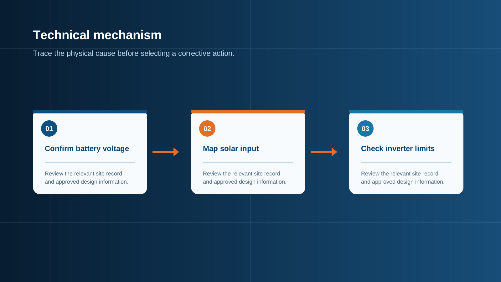
Technical diagram shown at a readable responsive scale.
Reading panel Voc and Vmp against the inverter window
Two module figures matter for matching. Open-circuit voltage, Voc, is the highest voltage the module produces with no load, and it defines the upper limit the electronics must survive. Maximum power voltage, Vmp, is the voltage at which the module delivers peak power under load, and it defines whether the tracker can actually operate. Both are quoted at standard test conditions of 25 degrees Celsius cell temperature.
Every charge controller or off-grid inverter datasheet states an absolute maximum input voltage and an operating tracking range. The string Voc at the coldest expected temperature must stay below the absolute maximum with margin, and the string Vmp at the hottest expected operating temperature must remain above the lower end of the tracking range. Designing to both limits at once is the whole of the sizing problem.
Cold-weather Voc rise and why it matters
Module voltage increases as cell temperature falls. The temperature coefficient of Voc is typically between minus 0.25 and minus 0.30 percent per degree Celsius, which means voltage rises by that percentage for every degree below 25 degrees. On a clear winter morning at minus 15 degrees, the cell is 40 degrees below the test condition, so Voc rises by roughly 10 to 12 percent.
Worked example: a module rated 41 V Voc, coefficient minus 0.28 percent per degree, in a string of six modules. At standard test conditions the string is 246 V. At minus 15 degrees the rise is 40 multiplied by 0.28, or 11.2 percent, so the string reaches roughly 274 V. If the controller maximum input is 250 V, that string is oversized and will fault on the coldest, sunniest morning of the year, which is exactly when the array is otherwise at its best.
- Always calculate Voc at the record low ambient temperature for the site, not the average winter temperature.
- Use the module temperature coefficient of Voc from the datasheet rather than a generic assumption.
- Keep a margin of at least ten percent below the absolute maximum input voltage.
- Remember that the maximum voltage event occurs at open circuit, for example immediately after a disconnect operates.
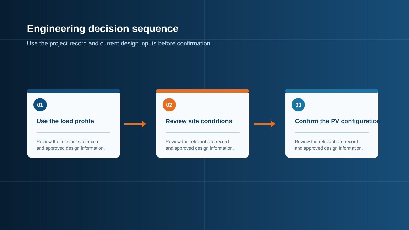
Technical diagram shown at a readable responsive scale.
How many panels fit a 12V, 24V or 48V input
The number of modules in series is bounded above by the cold Voc calculation and bounded below by the tracking window. Divide the controller maximum input voltage by the cold-corrected module Voc, then round down, to get the maximum series count. Divide the minimum tracking voltage by the hot-corrected module Vmp, then round up, to get the minimum series count. Any count between those two limits is electrically valid.
As a rough orientation for common equipment, a controller with a 150 V maximum input typically accepts two to three modern 40 V class modules in series. A 250 V maximum input accepts four to five. A 500 V class input accepts eight to ten. Once the series count is fixed, additional capacity is added by connecting further identical strings in parallel, and it is that parallel arrangement which creates the requirement for per-string overcurrent protection.
- Maximum series count equals controller maximum input voltage divided by cold-corrected module Voc, rounded down.
- Minimum series count equals lower tracking voltage divided by hot-corrected module Vmp, rounded up.
- Add capacity by paralleling identical strings, never by mixing series counts on one input.
- Check the controller maximum input current and maximum array power before finalising the parallel count.
String versus parallel wiring into the charge controller
Series wiring adds voltage while current stays at the level of one module. Parallel wiring adds current while voltage stays at the level of one string. For off-grid systems the general preference is to build voltage first, within the controller limit, because higher voltage and lower current mean thinner conductors and lower losses over the run from the array to the equipment room.
Parallel connections change the protection picture. With two strings in parallel a fault in one string can be fed by the other, and with three or more strings the available fault current becomes significant enough that per-string fuses are mandatory rather than optional. This is the point at which a proper combiner enclosure replaces a simple junction box: it provides individual string protection, a common busbar and a single switched output.
DC protection: fuses, disconnect and combining for off-grid arrays
An off-grid array needs the same DC protection discipline as a grid-connected one. Each string is protected by a gPV type fuse rated for photovoltaic duty, conventionally at not less than 1.25 times the module short-circuit current and below the module maximum series fuse rating. A load-break DC isolator allows the array to be disconnected safely for maintenance, and a DC surge protective device diverts induced transients away from the controller electronics.
Off-grid installations are frequently in exposed rural locations with long cable runs and no lightning protection nearby, which makes surge protection more important rather than less. The enclosure itself must match the environment, with an appropriate ingress protection class, ultraviolet-stable materials and the correct corrosion category for coastal or high-altitude sites.
- One gPV fuse per string, sized at 1.25 times Isc or above, within the module maximum series fuse rating.
- A load-break DC isolator rated for the full string voltage and current.
- A DC surge protective device with a continuous operating voltage above the maximum string voltage.
- An enclosure with the ingress and corrosion rating the installation site requires.
Sizing the balance of system around the array, not just the panels
Once the array configuration is fixed, the balance of system follows from three numbers: maximum string voltage at the coldest temperature, total array current at the combining point, and the physical distance from the array to the equipment. Those three values determine conductor cross-section, fuse rating, busbar capacity, isolator rating and surge protection class.
It is common in small off-grid projects to specify the modules and the electronics carefully and then improvise the connection between them. That is where preventable failures concentrate: undersized fuses that nuisance-trip, conductors that drop several percent of the harvest, and unprotected terminations that overheat. Treating the connection as engineered equipment rather than accessories is the single cheapest reliability improvement available.
Coordination with the battery bank and energy-storage control
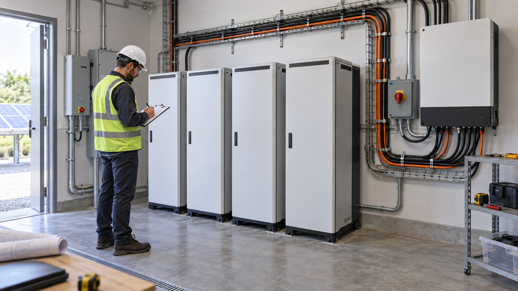
On the battery side of the controller the protection requirement changes character. Battery banks can deliver very high fault current, so the connection between bank and electronics needs a correctly rated DC breaker or fuse, a means of isolation for service, and clear labelling because the circuit cannot be de-energised by disconnecting a supply. An energy-storage control cabinet consolidates that switching, protection and monitoring into one assembly.
NEUTRON builds energy-storage control cabinets and DC control and protection assemblies that interface with third-party battery systems and charge electronics. The cabinet handles isolation, overcurrent protection, surge diversion and status monitoring on the direct current side, so the battery and the controller each sit behind properly rated switchgear rather than being wired directly to one another.
This is general technical guidance. Confirm final ratings, protection coordination, installation and applicable local requirements against current standards, manufacturer documentation and the approved project design.
Frequently asked questions
How many panels do I need for a 48V off-grid system?
Panel count is set by two separate calculations rather than by the nominal battery voltage. The series count is limited by the controller maximum input voltage divided by the cold-corrected module Voc, and it must also be high enough that the hot Vmp stays inside the tracking window. The parallel count is then set by the daily energy requirement and by the controller maximum input current and array power.
Do off-grid arrays need a combiner box?
A single string wired directly to a controller does not need one. As soon as two or more strings are connected in parallel, individual string overcurrent protection becomes necessary, because a fault in one string can be fed by the others, and a combiner enclosure is the standard way to provide it.
Discuss your PV requirement
Share the system voltage, string arrangement, inverter interface and installation environment. NEUTRON can review the equipment configuration around your project documentation.
Discuss a projectContinue learning
Explore related technical guidance in Solar PV.

Published from the approved Period 06 source package. Technical values and final design decisions must be verified against the current applicable standard, manufacturer documentation and approved project design.