
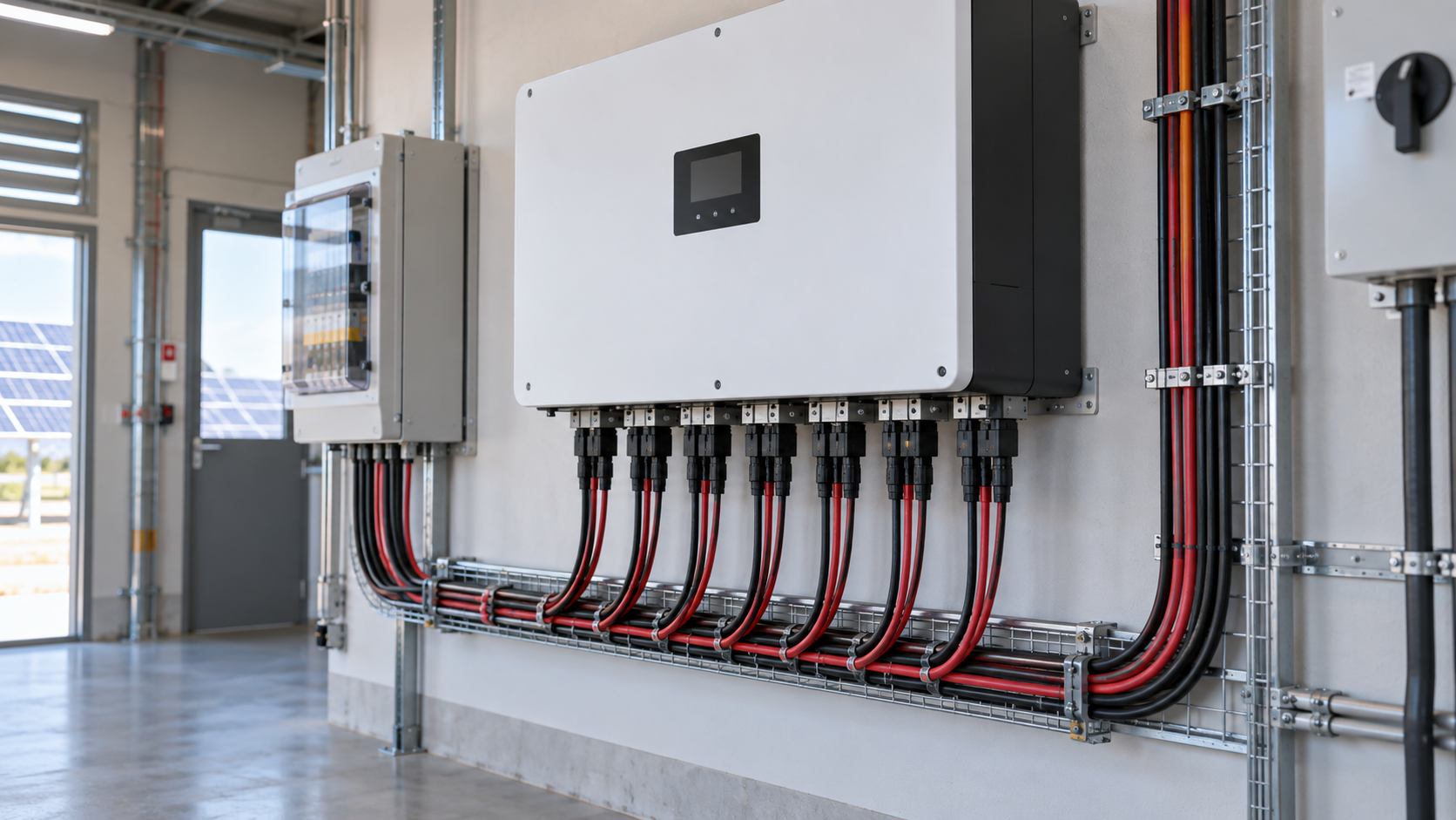
One tracking input versus two
A maximum power point tracker continuously adjusts the operating voltage of everything connected to it to find the point of highest power. Strings sharing one input therefore share one operating voltage. That is efficient when the strings are electrically similar and see the same irradiance, and wasteful when they are not, because the tracker must settle on a compromise that suits neither group.
Two independent inputs allow two different operating voltages simultaneously. The practical rule is straightforward: strings that behave identically can share an input, while strings that differ in orientation, tilt, module type or shading exposure should be separated. A single-input inverter forces every string onto one operating point, which is acceptable on a uniform single-plane array and a poor fit for anything more complex.
- Share an input: same orientation, same tilt, same module model, same series count, same shading exposure.
- Separate the inputs: different roof planes, different tilt, mixed module types, different string lengths, uneven shading.
Technical diagram shown at a readable responsive scale.
Splitting east and west panels
An east-west roof is the clearest case for separate tracking. East-facing modules peak in the morning while west-facing modules peak in the afternoon, so their optimum operating voltages diverge for most of the day. Combined on one input, the tracker chases a compromise and the weaker orientation is dragged off its own maximum. Separated onto two inputs, each group tracks independently and produces a broader, flatter daily generation curve.
The gain from splitting an east-west array across two inputs is commonly in the region of three to eight percent of annual energy, depending on the tilt and the balance between the two planes. The same reasoning applies to any combination of dissimilar planes: north-south splits, a steep facade section combined with a shallow roof, or a main array plus a small secondary block in a different orientation.
One important exception: never wire modules of different orientations into the same series string. Separate tracking inputs solve a voltage-optimisation problem between strings, but they cannot help a single string whose own modules are producing different currents. Within a string, uniformity is mandatory.
Why tracking inputs may differ in rating
It is a common and costly assumption that all tracking inputs on an inverter are identical. Many hybrid and three-phase units publish a higher maximum current on one input than another, or specify a maximum current per input alongside a lower total across all inputs combined. Others allow a defined number of parallel strings on the primary input and fewer on the secondary.
Three limits must be checked separately on the inverter datasheet before strings are allocated: maximum current per tracking input, maximum short-circuit current per input, and maximum total direct-current input current for the whole unit. A distribution that satisfies the per-input limits can still breach the total, and a plan that satisfies the current limits can still exceed the permitted number of parallel strings. Where inputs are asymmetric, the larger array group belongs on the higher-rated input.
- Maximum continuous current per tracking input.
- Maximum short-circuit current per tracking input, which governs fault tolerance.
- Maximum total direct-current input current across the whole inverter.
- Maximum permitted number of parallel strings per input, where stated.
Technical diagram shown at a readable responsive scale.
String count per input
Deciding how many strings feed one input is a matter of adding currents and comparing against the published limit. Each string contributes its maximum-power current in normal operation and its short-circuit current under fault conditions, and both sums must remain inside the respective per-input ratings with margin for high-irradiance events and, on bifacial arrays, for realised rear-side gain.
Voltage rules apply per string rather than per input, since paralleled strings share one voltage: every string on an input must have the same series count so their operating voltages match, and that series count must satisfy the cold-temperature open-circuit voltage limit and the tracking-window minimum at high temperature. Paralleling strings of unequal length onto one input forces the shorter strings off their optimum and can push current into unexpected paths.
A worked example
Consider a rooftop system with 24 modules: 14 on an east plane and 10 on a west plane, using modules with a maximum-power current of 13.5 amperes and a short-circuit current of 14.3 amperes. The inverter has two tracking inputs, the first rated 26 amperes continuous and the second 20 amperes, with a total direct-current limit of 40 amperes.
The east plane divides into two strings of seven modules, giving 27 amperes of operating current — above the 26-ampere limit of the first input, so this configuration fails. Reallocating to a single string of 14 modules on the east plane gives 13.5 amperes, comfortably within limits, provided the cold-corrected open-circuit voltage of 14 modules in series stays below the inverter maximum input voltage. The west plane becomes a single string of 10 modules at 13.5 amperes on the second input. Total operating current is 27 amperes against a 40-ampere ceiling, so the design passes all three checks.
The lesson is that string length and input allocation must be solved together. Reducing string count to satisfy a current limit only works if the resulting longer string still satisfies the voltage limit, and both checks are performed at the site's temperature extremes rather than at datasheet reference conditions.
DC protection per input
Protection follows the distribution plan rather than the inverter chassis. Every string needs its own overcurrent device sized on its short-circuit current, typically a photovoltaic-rated fuse at no less than 1.25 times that value and within the module manufacturer's stated maximum series fuse rating. This applies regardless of which tracking input the string ultimately feeds.
Where several strings are paralleled onto one input, individual string protection also prevents a weak or faulted string from being back-fed by its healthy neighbours. Each tracking input additionally needs a load-break isolation point so that group can be worked on safely while the rest of the array remains live, and surge protection must be provided on the direct-current side with a protection level and continuous operating voltage matched to the maximum system voltage.
- One overcurrent device per string, sized on corrected short-circuit current, never one shared device per input.
- One isolation point per tracking input group, clearly labelled and rated for direct-current duty.
- Direct-current surge protection coordinated to the maximum system voltage, close to the combining point.
- Separate output conductors per input, each sized for that group's aggregated current.
Combiner box organisation
The cleanest arrangement mirrors the tracking structure inside the enclosure. Strings destined for the same input are grouped on adjacent terminals, protected by their own fuses, and collected onto a busbar section serving only that input, with its own isolation device and its own output conductor. Where two inputs are served from one enclosure, that means two electrically separate collection sections sharing a single housing, earthing system and surge protection stage.
Clear labelling is what makes this maintainable. Marking each terminal with both its string identifier and its destination input means a technician measuring a low string current knows immediately which group and which output feed are involved. Where per-string current monitoring is fitted, grouping the measurement by input makes deviation detection straightforward, because strings on the same input should read almost identically.
- One fused terminal group and one busbar section per tracking input.
- One isolation device and one output feed per input group.
- Label every terminal with string identifier and destination input.
- Group per-string monitoring by input so deviations are directly comparable.
Avoiding common distribution errors
Most distribution faults fall into a short list. Mixing orientations inside one series string is the most damaging, because no tracking arrangement can correct it. Paralleling strings of unequal series count onto one input is next, since the shorter strings are pulled away from their optimum permanently. Assuming symmetrical input ratings is a frequent oversight that only reveals itself as current limiting on bright days.
The remaining errors are checking the per-input limit while ignoring the total inverter limit, sizing string fuses on operating current instead of short-circuit current, and omitting a per-input isolation point so that any maintenance requires shutting the whole array down. Each of these is caught by working through the voltage, current and total checks with the site's temperature extremes before the equipment is ordered. NEUTRON reviews the array layout and inverter input data and prepares a configuration discussion for combining and protection equipment partitioned to match the tracking plan.
This is general technical guidance. Confirm final ratings, protection coordination, installation and applicable local requirements against current standards, manufacturer documentation and the approved project design.
Frequently asked questions
How many strings per MPPT?
The answer comes from current, not from a rule of thumb. Add the maximum-power currents of the strings you intend to parallel and compare the total with the published maximum continuous current for that tracking input, then repeat the exercise with short-circuit currents against the input's short-circuit rating.
Do MPPT inputs need separate fuses?
Protection is applied per string, not per input, so every string needs its own overcurrent device sized at no less than 1.25 times its short-circuit current using a photovoltaic-rated fuse, kept within the module manufacturer's maximum series fuse rating.
Discuss your PV requirement
Share the system voltage, string arrangement, inverter interface and installation environment. NEUTRON can review the equipment configuration around your project documentation.
Discuss a projectContinue learning
Explore related technical guidance in Solar PV.


Published from the approved Period 06 source package. Technical values and final design decisions must be verified against the current applicable standard, manufacturer documentation and approved project design.