

What the cloud-edge effect is
Standard test conditions define module ratings at an irradiance of 1000 watts per square metre. On a clear day at a good location the plane-of-array irradiance approaches that figure around solar noon. On a partly cloudy day, however, irradiance at the array can briefly exceed it, because the array receives direct beam radiation from the clear sky at the same moment as strongly scattered radiation from a nearby bright cloud edge.
The event is short-lived, typically lasting a few seconds to a couple of minutes, and it repeats many times through a day of scattered cumulus cloud. Because the modules respond to irradiance almost instantaneously, output follows the spike, which is why monitoring traces on such days show a spiky sawtooth pattern with peaks above the smooth clear-sky curve.
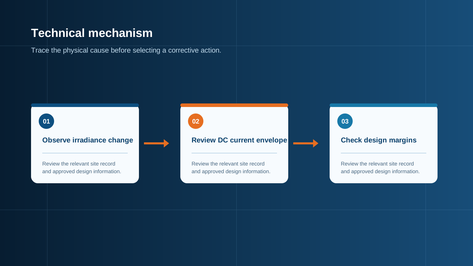
Technical diagram shown at a readable responsive scale.
Why irradiance briefly reaches 1200 watts per square metre
The mechanism is additive. Direct beam radiation arriving unobstructed from the solar disc contributes its normal share. Simultaneously, the illuminated edge and side wall of a cumulus cloud acts as a large diffuse reflector, adding scattered radiation to the same plane. When the geometry aligns so the array sees the sun and the bright cloud flank at once, total irradiance in the plane of the array rises above the clear-sky value.
Measured plane-of-array values of 1150 to 1250 watts per square metre are commonplace in such conditions, and instrumented studies have recorded short excursions beyond 1400 watts per square metre in high-albedo environments such as snow-covered or desert sites. Ground and snow reflectance reinforce the effect, and bifacial modules capture some of that reflected component on the rear face as well.
- Direct beam and cloud-edge scattered radiation add in the plane of the array.
- Typical peaks: 1150 to 1250 watts per square metre; extremes above 1400 in high-albedo conditions.
- Duration: seconds to a few minutes, repeating many times through a broken-cloud day.
- Snow, sand and bright rooftops raise the reflected contribution further.
Panels exceeding nameplate output
Module current is very nearly proportional to irradiance, so an irradiance of 1200 watts per square metre yields approximately 1.2 times the rated short-circuit and operating current. Voltage rises only slightly, being logarithmically related to irradiance. Power therefore rises broadly in proportion to current, which means a module can momentarily deliver fifteen to twenty percent above its nameplate rating.
There is a secondary factor that amplifies the effect. Cloud-edge events often occur when the modules have been shaded moments earlier and are therefore cooler than in steady sunshine. Because voltage rises as temperature falls, a cool module at high irradiance produces both higher current and higher voltage than either condition alone would suggest. This is the combination that produces the highest instantaneous output an array will ever see.
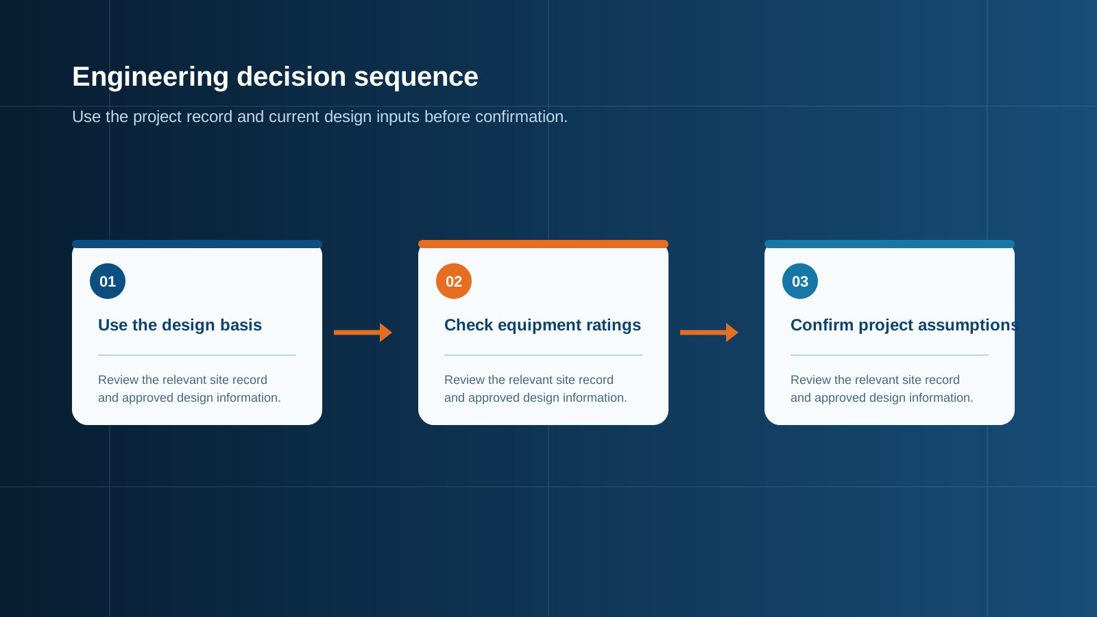
Technical diagram shown at a readable responsive scale.
Impact on string fuses and protection
This is where the phenomenon becomes an engineering constraint. A string fuse sized exactly at module short-circuit current will carry roughly 1.2 times its rating during an over-irradiance event, and repeated excursions of that kind gradually age the fuse element even when no single event causes it to operate. The result appears in service as apparently random string outages after months of normal operation.
The conventional 1.25 factor applied when sizing gPV fuses exists precisely to accommodate this. Sizing at not less than 1.25 times short-circuit current means the device carries about ninety-six percent of its rating during a 1200 watt per square metre event, which is within its continuous capability. For bifacial modules the rear-side gain must be applied first, because it stacks with the over-irradiance factor rather than replacing it.
- A fuse sized at exactly Isc carries roughly 1.2 times rating during an over-irradiance event.
- Repeated excursions age the fuse element and produce unexplained string outages later.
- The 1.25 sizing factor exists to absorb these peaks; it is not a comfort margin to be trimmed.
- For bifacial modules, apply rear-side gain to Isc before applying the 1.25 factor.
Impact on inverter clipping
On the conversion side the effect is the opposite of a problem. An inverter limits its output to its rated alternating-current capacity, so when array output spikes above that limit the surplus is simply not converted. The array is held slightly away from its maximum power point for the duration, and no equipment is stressed. Modern conversion equipment is designed to operate in this limited state indefinitely.
The energy consequence is small because the events are brief. Where the direct-to-alternating-current ratio is moderate, cloud-edge peaks contribute only a fraction of a percent of annual limitation. Where the ratio is already high, the peaks fall into a region that is limited anyway for much of the day, so they add nothing. The array-side equipment, by contrast, must carry the full spike current because it sits upstream of any limiting action.
Designing margin into the balance of system
The design principle is straightforward: everything upstream of the conversion stage is sized for peak current, and only the conversion stage itself may rely on limiting. That means string fuses, string conductors, combining busbar, isolators and surge protective devices are all dimensioned for the over-irradiance case rather than for standard test conditions.
In practice this translates into a checklist. Apply the 1.25 factor to string short-circuit current before selecting fuses, and add bifacial gain beforehand where relevant. Size string conductors for the fused current with acceptable temperature rise. Rate the busbar for the sum of all protected string currents at peak, not at nominal. Confirm the isolator continuous current rating covers the same aggregate. And verify the surge protective device continuous operating voltage against string open-circuit voltage at the lowest expected temperature, since the coolest and brightest moments coincide.
- Fuses: 1.25 times short-circuit current, with bifacial gain applied first.
- Conductors: rated for the fused current with acceptable temperature rise inside the enclosure.
- Busbar: rated for the aggregate of all protected strings at peak current.
- Isolator and surge protective device: rated for peak aggregate current and cold open-circuit voltage.
Monitoring and where it pays off
String-level monitoring is what turns this phenomenon from a mystery into data. With per-string current measurement in the combiner enclosure, over-irradiance peaks are visible as short synchronous excursions across all strings, which distinguishes them immediately from a genuine fault, where one string diverges from the others. Without that granularity, an operator sees only an array-level figure and has no way to attribute a change.
The payoff is diagnostic speed. When a string does eventually go offline, monitoring history shows whether it had been running consistently near the top of its band, which points toward a marginal fuse rating rather than a wiring fault. On larger plants this is the difference between a targeted intervention and a full array inspection.
Sizing protection for peak, not average
The summary is a single principle. Average conditions determine the energy yield and therefore the financial model, while peak conditions determine the equipment rating and therefore the reliability. Sizing protection to average irradiance produces a system that works most of the time and fails on the brightest days, which is the least acceptable failure pattern because it coincides with peak production value.
NEUTRON configures PV combiner equipment and DC control and protection assemblies against peak-case inputs: string short-circuit current including bifacial gain, the applicable sizing factor, aggregate busbar current, maximum string open-circuit voltage at the lowest site temperature, and the site ingress and corrosion class. Supplying those figures with the enquiry means the enclosure is built for the array's worst moment rather than its typical one.
This is general technical guidance. Confirm final ratings, protection coordination, installation and applicable local requirements against current standards, manufacturer documentation and the approved project design.
Frequently asked questions
Can panels really exceed their rated power?
Yes, briefly. Module ratings are defined at an irradiance of 1000 watts per square metre, and on partly cloudy days the plane-of-array irradiance can reach 1150 to 1250 watts per square metre when direct beam radiation and radiation scattered from a bright cloud edge arrive together. Since current is nearly proportional to irradiance, output rises about fifteen to twenty percent above nameplate.
How does it affect inverter clipping?
The conversion stage limits its output to rated alternating-current capacity, so a spike above that limit is simply not converted. The array is held briefly away from its maximum power point and no equipment is stressed; modern conversion equipment can operate in that limited state indefinitely.
Discuss your PV requirement
Share the system voltage, string arrangement, inverter interface and installation environment. NEUTRON can review the equipment configuration around your project documentation.
Discuss a projectContinue learning
Explore related technical guidance in Solar PV.


Published from the approved Period 06 source package. Technical values and final design decisions must be verified against the current applicable standard, manufacturer documentation and approved project design.