
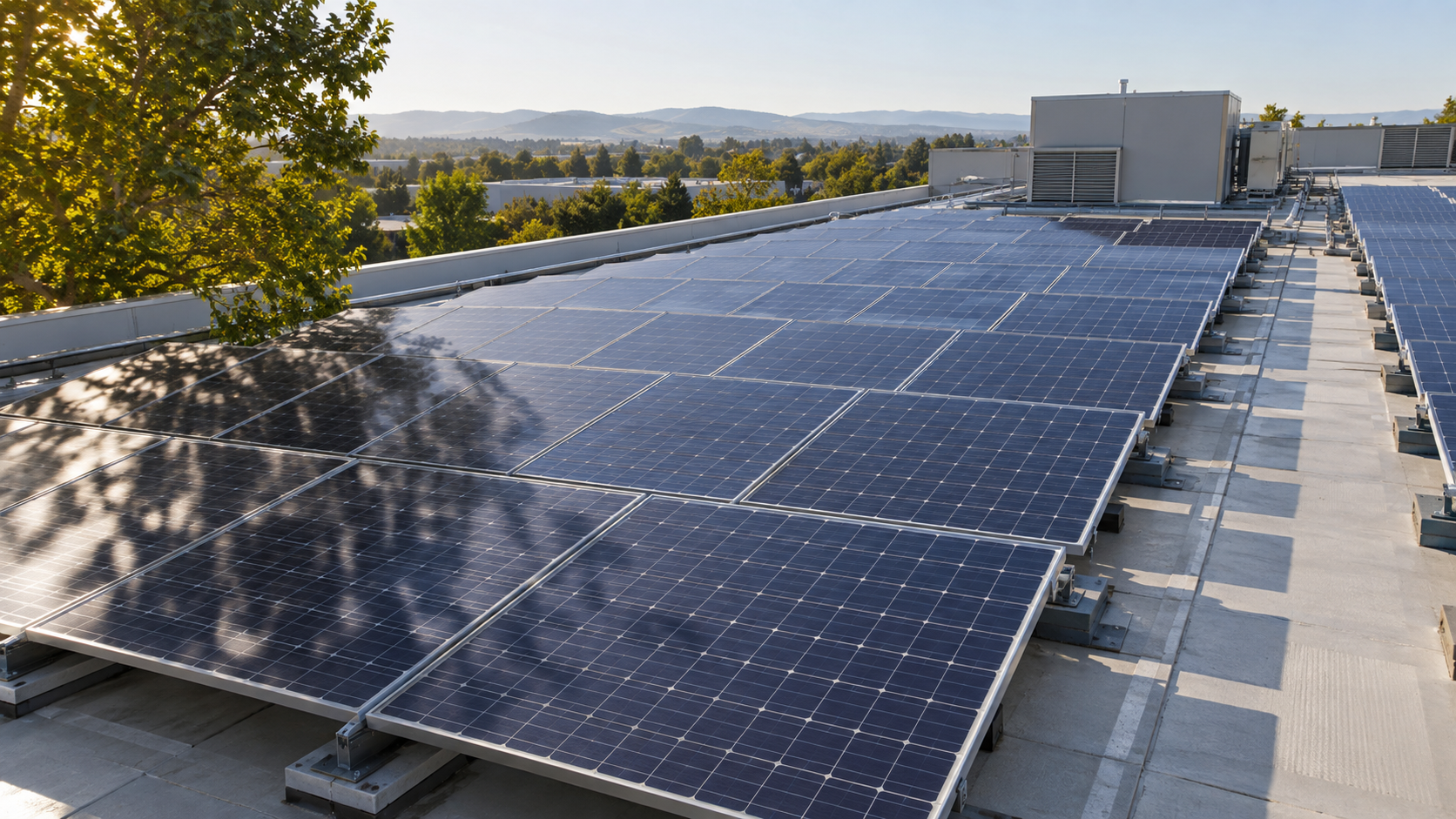
Why partial shade hurts more than you think
In a series string, current is common to every module. A module that is partly shaded can only pass the current its illuminated cells can produce, so it becomes a bottleneck for the whole string. Shade one substring heavily and the current available to the string collapses towards that limit, even though every other module in the string is in full sun. This is why a chimney shadow across one module in a twenty-module string can cost far more than five percent of that string's output.
The effect is also time-dependent. Shadows move, lengthen and change shape through the day and across the seasons, so a roof that looks clear at noon in June may lose the first and last hours of production for months in winter. Any shading assessment should therefore consider the worst-case season, not a single midday snapshot.
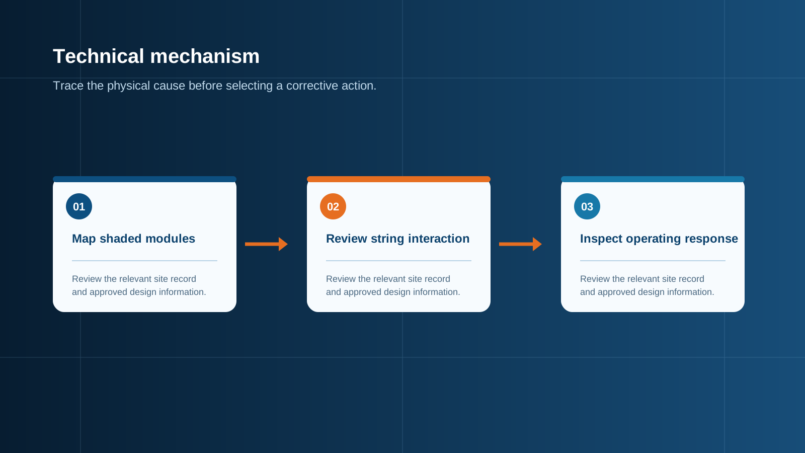
Technical diagram shown at a readable responsive scale.
Bypass diodes and how they work
Every modern crystalline module contains bypass diodes, typically three, each protecting one substring of cells. When a substring becomes strongly shaded and starts to reverse-bias, its diode conducts and provides an alternative path so the string current can flow around the affected cells rather than through them. This limits the loss and, more importantly, prevents the shaded cells from dissipating the full string current as heat.
Half-cut cell modules, which split the cells into two parallel halves, react better to shading that falls along one edge, because one half can continue to operate while the other is bypassed. The layout of the shadow relative to the cell string direction therefore matters as much as the shadow area.
- A conducting diode removes the contribution of its whole substring, so the module output falls in coarse steps of roughly one third rather than smoothly.
- The diode protects the cells but does not recover the lost energy — it converts a potentially damaging condition into a manageable production loss.
- Diodes are a wear item. A failed open diode leaves cells unprotected against hot spots; a failed short diode permanently disables a substring.
Series versus parallel shading behaviour
In series wiring, voltages add and current is shared, so shading propagates: the shaded module limits the current of every module connected in that series path. In parallel wiring, currents add and voltage is shared, so a shaded branch simply contributes less current while the other branches carry on unaffected. Parallel configurations are therefore inherently more tolerant of localised shade.
Practical arrays are almost always series-parallel: several series strings connected in parallel at the combining point. The design lever is how modules are grouped. Keeping all modules that share a shading pattern within the same string, and separating them from clear-sky modules, confines the loss to one string instead of spreading it across several. Mixing shaded and unshaded modules in the same series path is the layout error that causes the largest avoidable losses.
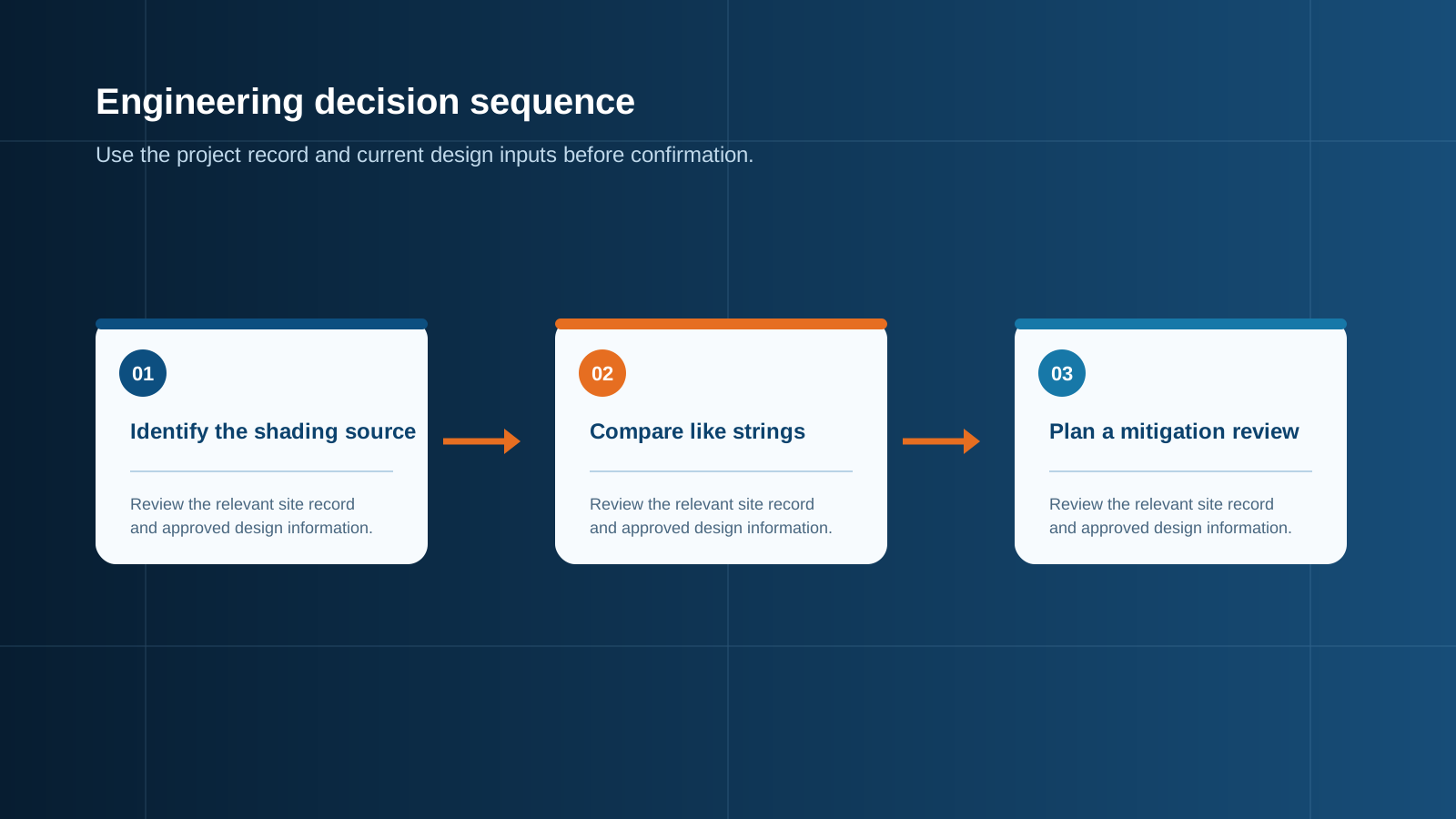
Technical diagram shown at a readable responsive scale.
Hot-spot risk and protection
When a shaded cell is forced to carry current it cannot generate, it operates in reverse bias and dissipates power as heat. The result is a hot spot: a localised temperature rise that can discolour the encapsulant, crack the cell, damage the backsheet and in severe cases create an open circuit or a fire risk. Bypass diodes exist specifically to cap this condition, which is why diode integrity is a safety matter and not merely a yield matter.
Persistent hard shading — a pipe, a bracket, a permanently soiled edge — is more dangerous than moving shade because the thermal stress is repeated in the same place every day. Where hard shading cannot be removed, the affected modules should be relocated to their own string, or the layout revised, rather than left to cycle their diodes indefinitely.
String-level versus module-level mitigation
There are two families of response. String-level mitigation reorganises the electrical layout: group modules by shading exposure, use shorter strings on the affected planes, and assign those strings to their own tracking input so the tracker can find a working operating point without dragging clear strings with it. This costs nothing but design attention and adds no components to maintain.
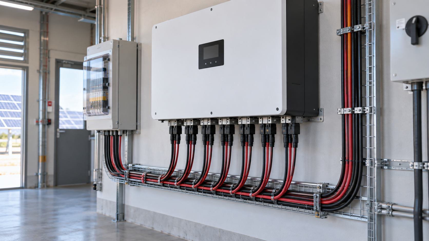
Where module-level electronics from other manufacturers are used, NEUTRON equipment sits below them: the direct-current combining, isolation and surge protection stage that collects the strings and delivers a protected feed to the inverter.
- String-level: regroup modules, shorten affected strings, dedicate a tracking input, adjust row pitch or module position to clear the obstruction.
- Module-level electronics: third-party optimisers or micro-conversion devices let each module operate independently, recovering more energy on badly shaded roofs at the cost of more electronics on the roof.
- Physical: trim vegetation, relocate rooftop plant, raise or reposition the array to clear a fixed obstruction — always the cheapest fix over the plant lifetime.
Fuse and combiner implications
A common misconception is that shading allows smaller string protection because the shaded string produces less current. It does not. String overcurrent protection is sized on the short-circuit current of the string under full irradiance, with the usual practice being a photovoltaic-rated fuse at no less than 1.25 times the string short-circuit current. Shade is intermittent; the fuse must survive the unshaded condition, which will occur every clear day.
What shading does change is the fault behaviour to consider. Where several strings are paralleled, a low-producing shaded string can be back-fed by its neighbours, so each string needs its own protective device rather than a single device on the combined output. Reverse-current capability, correct device selection for direct-current duty and clear per-string identification all become more important on arrays with uneven irradiance.
- Size the string fuse on full-sun short-circuit current, never on the shaded operating current.
- Protect every parallel string individually so a weak string cannot be back-fed by the others.
- Use devices rated for direct-current duty and for the maximum system voltage, and keep a defined isolation point for the sub-array.
- Where per-string measurement is provided at the combining point, it becomes the primary tool for detecting shading and soiling losses.
Layout to minimise shade loss
Good layout begins with an obstruction survey covering the low-sun months. From there, three rules do most of the work: keep a clearance around obstructions rather than crowding modules against them, set row pitch on tilted arrays so that front rows do not shade the row behind during the productive part of the day, and orient module rows so that any unavoidable shadow crosses the short dimension of the cell strings rather than running along them.
On rooftops, plant, ducts and safety rails should be treated as fixed shading obstacles at the design stage. On ground-mounted fields, perimeter fencing, cabinets and vegetation growth need the same treatment. It is far cheaper to move a module during design than to explain a permanent production shortfall afterwards.
Monitoring string health
Shading losses are invisible at the plant meter because they blend into normal weather variation. The reliable way to see them is per-string current measurement at the combining point, compared string against string. Because parallel strings share the same irradiance and the same operating voltage, a string that consistently reads low compared with its neighbours is telling you something specific: shading, soiling, a failed bypass diode, a poor termination or a degraded module.
Setting a simple deviation threshold against the string average turns this into an actionable alarm, and recording the daily profile distinguishes a moving shadow, which appears at the same time each day, from a hardware fault, which persists all day. Specifying string-level monitoring inside the combining enclosure at procurement is far less expensive than retrofitting it after commissioning.
This is general technical guidance. Confirm final ratings, protection coordination, installation and applicable local requirements against current standards, manufacturer documentation and the approved project design.
Frequently asked questions
Do bypass diodes prevent shade loss?
No. Bypass diodes limit damage, not loss. When a substring of cells is strongly shaded and begins to reverse-bias, its diode conducts and lets the string current flow around those cells, which prevents dangerous heating.
How does shade affect fuses?
It does not reduce the required rating. String overcurrent protection is sized on the full-irradiance short-circuit current of the string, typically at no less than 1.25 times that value using a photovoltaic-rated fuse. Shading is intermittent, so the device must survive the clear-sky condition.
Discuss your PV requirement
Share the system voltage, string arrangement, inverter interface and installation environment. NEUTRON can review the equipment configuration around your project documentation.
Discuss a projectContinue learning
Explore related technical guidance in Solar PV.

Published from the approved Period 06 source package. Technical values and final design decisions must be verified against the current applicable standard, manufacturer documentation and approved project design.