

The specs that decide your design
Of the dozens of figures on a typical datasheet, six do the heavy lifting: open-circuit voltage, maximum-power voltage, short-circuit current, maximum-power current, rated power, and the temperature coefficients. Everything else — dimensions, weight, mechanical load ratings, connector type, certifications — matters for mounting and compliance but does not change the electrical calculation.
- Open-circuit voltage decides the maximum number of modules per series string.
- Maximum-power voltage decides whether the string stays inside the inverter tracking window.
- Short-circuit current decides string fuse rating, conductor size and busbar rating.
- Maximum-power current decides normal operating current and voltage-drop calculations.
- Rated power drives energy modelling and inverter ratio decisions.
- Temperature coefficients convert all of the above from laboratory values into site values.
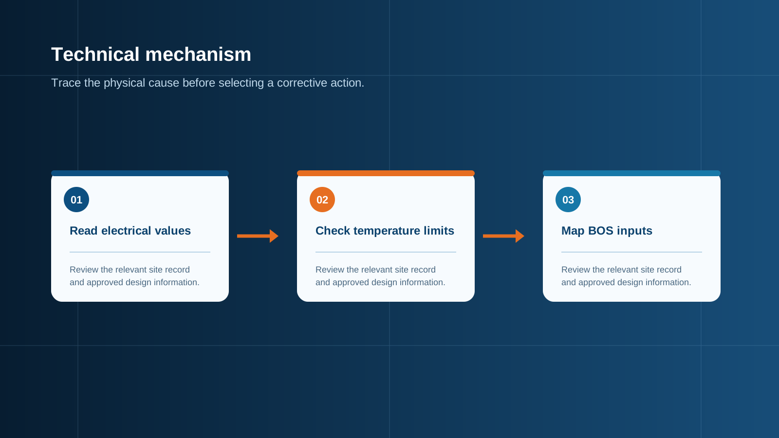
Technical diagram shown at a readable responsive scale.
Open-circuit and maximum-power voltage
Open-circuit voltage is the voltage across the module terminals with nothing connected — the highest voltage the module can present. It is the safety-critical figure, because the series sum of open-circuit voltages must never exceed the module's maximum system voltage rating, the inverter's maximum input voltage, or the rating of any isolation, surge protection or fuse device in the string path. Maximum-power voltage is the lower voltage at which the module delivers peak power under load, typically around eighty percent of open-circuit voltage.
The crucial point is that both figures rise as temperature falls. Datasheet values are quoted at 25 degrees Celsius cell temperature, but a string energised on a cold, clear winter morning can sit well below that. Maximum series count must therefore be calculated at the lowest expected ambient temperature at the site, using the open-circuit voltage temperature coefficient. Designing on the 25-degree figure is the classic error that produces an over-voltage fault the first cold morning after commissioning.
Short-circuit and maximum-power current
Short-circuit current is the current the module delivers with its terminals shorted, under standard test irradiance of 1000 watts per square metre. It is the design basis for protection: string overcurrent devices are sized on it, conductors are selected to carry it, and busbars are rated for the sum of it across all combined strings. Maximum-power current is the operating current at the peak power point, slightly lower, and it is what determines normal running losses and voltage drop.
Unlike voltage, current scales almost linearly with irradiance and moves only slightly with temperature. That has two consequences. Brief high-irradiance events, such as a bright cloud edge lifting total irradiance above the standard test level, push current above the datasheet value. And where bifacial modules are used, rear-side irradiance adds to the front contribution, so the effective short-circuit current is higher than the front-side figure printed on the datasheet. Both effects must be included before a fuse is chosen.
- Size string overcurrent protection at no less than 1.25 times the string short-circuit current, using a photovoltaic-rated fuse.
- Correct the short-circuit current upward for realised rear-side gain on bifacial modules.
- Rate the output busbar for the summed short-circuit current of all combined strings, derated for enclosure internal temperature.
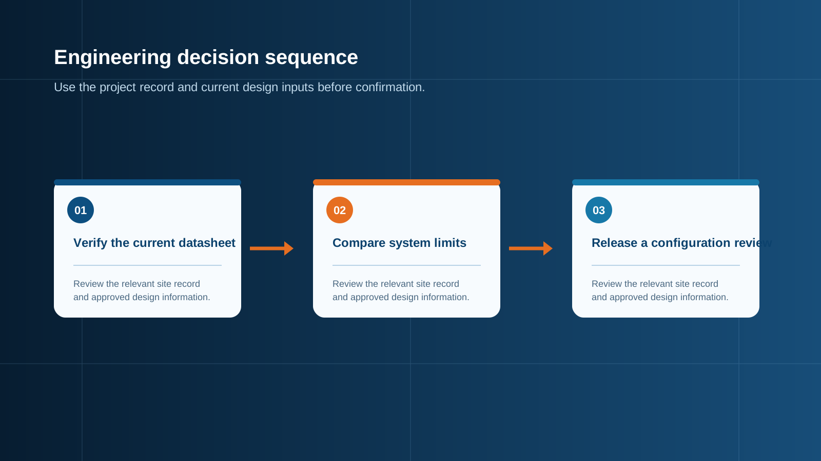
Technical diagram shown at a readable responsive scale.
Rated power and the standard-condition split
Rated power is the product of maximum-power voltage and maximum-power current under standard test conditions: 1000 watts per square metre irradiance, 25 degrees Celsius cell temperature and a defined air mass. Those conditions are a laboratory reference, not a description of a roof. A module on a sunny roof commonly runs at a cell temperature of 45 to 65 degrees Celsius, which is why real output sits below the nameplate figure most of the time.
Better datasheets also publish figures at nominal operating cell temperature, a more representative condition with lower irradiance and elevated cell temperature. Those values typically land around seventy-five to eighty percent of the standard-condition rating and are far more useful for energy expectations. Power tolerance also matters: a rating quoted with a zero to plus-five-watt tolerance means every module meets or exceeds nameplate, whereas a symmetrical tolerance means some modules ship below it.
Temperature coefficients
Three coefficients appear on most datasheets, expressed as a percentage change per degree Celsius from the 25-degree reference. The power coefficient is negative, commonly around -0.29 to -0.40 percent per degree, meaning output falls as the module heats. The open-circuit voltage coefficient is also negative, commonly around -0.24 to -0.30 percent per degree, meaning voltage rises as temperature falls. The short-circuit current coefficient is small and positive, typically around +0.04 percent per degree, and rarely changes a design decision.
The voltage coefficient is the one that governs safety. Take a module with an open-circuit voltage of 50 volts and a coefficient of -0.27 percent per degree. At a site with a minimum expected temperature of -15 degrees, the temperature difference from reference is 40 degrees, giving a voltage rise of about 10.8 percent, so each module can present roughly 55.4 volts. Against a 1500-volt system limit that allows 27 modules in series, whereas the uncorrected calculation would suggest 30. Using the higher figure would exceed the system voltage rating on the coldest morning of the year.
Efficiency and tolerances
Module efficiency is rated power divided by module area at standard conditions. Its practical value is spatial: higher efficiency means more watts in the same footprint, which matters where roof area or land is constrained. It does not by itself mean the module produces more energy per watt installed — that depends on temperature behaviour, low-light response and degradation rate.
Alongside efficiency, check the mechanical and environmental data that affects the electrical enclosure downstream: connector type and rating, maximum series fuse rating stated by the manufacturer, module maximum system voltage, and the certification list. The manufacturer's stated maximum series fuse rating is a ceiling that must not be exceeded, and it is a genuine constraint that is frequently overlooked when protection is selected.
Using the datasheet to size strings
The procedure is short and mechanical. First, take the open-circuit voltage and correct it for the site's minimum expected temperature using the voltage coefficient, then divide the lower of the module maximum system voltage and the inverter maximum input voltage by that corrected figure and round down — that is the maximum series count. Second, take the maximum-power voltage, correct it for the site's maximum expected cell temperature, and confirm the string still sits above the bottom of the inverter tracking window at that temperature.
Third, take the short-circuit current, correct it for rear-side gain where applicable, and apply the 1.25 factor to obtain the minimum string fuse rating, then check that result against the manufacturer's maximum series fuse rating. Fourth, multiply the corrected string current by the number of parallel strings to get the busbar requirement. Four calculations, all taken from the same page, and the string design is complete.
- Maximum series count from cold-corrected open-circuit voltage against the lower of module and inverter voltage limits.
- Minimum series count from hot-corrected maximum-power voltage against the tracking window.
- String fuse rating from 1.25 times corrected short-circuit current, capped by the maximum series fuse rating.
- Busbar and output rating from corrected string current multiplied by parallel string count.
Feeding the numbers into BOS selection
Once the string design is fixed, the combining and protection specification is fully determined. The maximum system voltage sets insulation level, isolation device rating and surge protective device selection. The corrected string current sets fuse rating, holder rating and input conductor size. The parallel string count sets input count, terminal count and busbar cross-section. Site conditions set the enclosure environmental class and the internal temperature derating.
Presenting these four figures to a supplier — maximum system direct-current voltage, corrected string short-circuit current, number of input strings, and site environmental class — removes ambiguity and produces equipment built for the modules actually being installed. NEUTRON reviews the module data and site conditions and prepares a configuration discussion for the combining, protection and distribution equipment that matches them.
This is general technical guidance. Confirm final ratings, protection coordination, installation and applicable local requirements against current standards, manufacturer documentation and the approved project design.
Frequently asked questions
What is Voc vs Vmpp?
Open-circuit voltage is the voltage a module presents with nothing connected — its highest possible output voltage. Maximum-power voltage is the lower voltage at which the module delivers peak power under load, usually around eighty percent of the open-circuit figure.
How do I read temp coefficient?
Coefficients are percentage changes per degree Celsius relative to the 25-degree reference. Power and open-circuit voltage coefficients are negative, so output falls as the module heats and voltage rises as it cools. The short-circuit current coefficient is small and positive.
Discuss your PV requirement
Share the system voltage, string arrangement, inverter interface and installation environment. NEUTRON can review the equipment configuration around your project documentation.
Discuss a projectContinue learning
Explore related technical guidance in Solar PV.


Published from the approved Period 06 source package. Technical values and final design decisions must be verified against the current applicable standard, manufacturer documentation and approved project design.