

Why PV needs dedicated DC protection
An alternating-current fault current passes through zero twice per cycle, and conventional breakers rely on that instant to interrupt the arc. Direct current does not, so a direct-current arc must be forced to extinguish by stretching and cooling it. A device not designed for that duty may fail to interrupt at all, sustaining an arc inside the enclosure. This is the single most important reason photovoltaic protection uses purpose-designed devices.
The second reason is that an array is a current-limited generator. A short circuit on a string produces only slightly more than the short-circuit current the modules can deliver, perhaps 1.1 to 1.2 times the rated value, not the many multiples available from a transformer-fed circuit. A protective device sized generously will therefore never operate, and the fault will persist as a heating condition rather than an interruption. Correct sizing has to sit in a narrow band: high enough not to nuisance-operate, low enough to actually clear.
- Direct current has no zero crossing, so arc interruption requires purpose-designed devices.
- Array fault current is limited to slightly above short-circuit current, so oversized devices never operate.
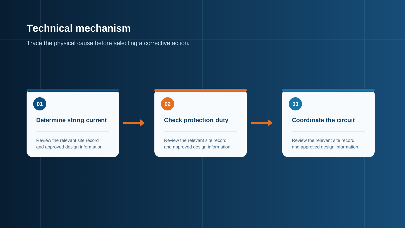
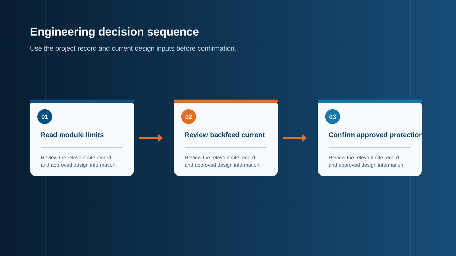
- On a shared busbar, fault current can be fed backwards into a faulted string by the parallel strings.
- Photovoltaic circuits operate near their rated current for hours at a time, so continuous duty derating matters.
Technical diagram shown at a readable responsive scale.
DC string fuses: gPV type and the 1.25 times Isc rule
String protection uses gPV type fuses, defined in IEC 60269-6 specifically for photovoltaic service. The conventional sizing rule sets the nominal rating at not less than 1.25 times the module short-circuit current, and simultaneously at not more than the maximum series fuse rating printed on the module label. The lower bound prevents operation during normal peak output; the upper bound ensures the fuse still protects the module and its wiring.
Worked example: a module rated 13.9 A short-circuit current with a maximum series fuse rating of 25 A. The floor is 1.25 multiplied by 13.9, which is 17.4 A. The next standard rating above that is 20 A, which is comfortably below the 25 A ceiling, so a 20 A gPV fuse is correct. Choosing 15 A would fall below the calculated floor and would operate on bright cold days; choosing 30 A would exceed the module ceiling and leave the string effectively unprotected.
- Sizing floor: 1.25 times module short-circuit current, then round up to the next standard rating.
- Sizing ceiling: the maximum series fuse rating printed on the module label.
- Rated voltage must equal or exceed maximum string open-circuit voltage at the lowest expected temperature.
- For bifacial modules apply the rear-side gain to short-circuit current before calculating the floor.
NEC 690.9 and IEC 62548 requirements
In North American practice, Article 690.8 of the National Electrical Code establishes the maximum circuit current as 1.25 times the rated short-circuit current, and Article 690.9 requires overcurrent protection on photovoltaic circuits, with a further 1.25 continuous-duty factor applied when sizing the device for conductors and equipment not rated for continuous operation at full load. The combination is what gives rise to the commonly quoted 1.56 factor in some designs.
In IEC practice, IEC 62548 covers photovoltaic array design requirements and addresses string overcurrent protection, cable sizing and the conditions under which string fuses are required. It works together with IEC 60269-6 for the gPV fuse characteristics themselves and with IEC 61439 for the assembly in which the devices are installed. The practical outcome of both regimes is similar: a device above 1.25 times short-circuit current and below the module maximum series fuse rating, rated for the full array voltage.
- NEC 690.8: maximum circuit current equals 1.25 times rated short-circuit current.
- NEC 690.9: overcurrent protection required, with continuous-duty factor applied for device sizing.
- IEC 62548: array design requirements including string protection and cable sizing.
- IEC 60269-6: gPV fuse characteristics; IEC 61439: the assembly containing the devices.
Technical diagram shown at a readable responsive scale.
gPV versus gG fuse differences
A gG fuse is a general-purpose device intended for alternating-current distribution circuits. A gPV fuse is designed for direct-current photovoltaic service. The differences are substantial: gPV devices are tested and rated for direct-current voltage up to 1000 or 1500 V, they are qualified to interrupt the low-multiple fault currents that arrays actually produce, and their time-current characteristic is shaped for a generator that sits near rated current for long periods.
Substituting a gG fuse in a string position is a genuine safety problem rather than a technical nicety. A gG device may carry a direct-current rating far below the string voltage, or none at all, and may be unable to interrupt a sustained direct-current arc. Where such a substitution has been made in the field, the correct action is replacement, not observation.
Breaking capacity and fault current
Breaking capacity is the maximum current a device can interrupt safely. On the array side of a system the available fault current is modest, so breaking capacity is rarely the binding constraint; string devices are typically qualified well above anything the array can deliver. The situation reverses once a battery or the grid is present, because both can supply fault currents of many kilo-amperes.
Two positions therefore demand attention. On the direct-current side, any connection to a battery bank must be protected by a device with a breaking capacity above the battery prospective short-circuit current, which for a large lithium bank can be several kilo-amperes. On the alternating-current side, the breaker must have a breaking capacity above the prospective fault current at that point in the installation, a figure obtained from the network operator or from a calculation of the supply impedance.
- Array-side devices: fault current is limited, so breaking capacity is seldom the binding constraint.
- Battery-side devices: prospective fault current can reach several kilo-amperes and governs selection.
- Alternating-current side: breaking capacity must exceed the prospective fault current at that point.
- Rated direct-current voltage must always be checked separately from breaking capacity.
AC breaker sizing on the output side
The alternating-current breaker downstream of the inverter is sized against the inverter continuous output current, not against array capacity. Take the rated continuous alternating-current output, apply the continuous-duty factor required by the governing code, and select the next standard breaker rating above the result while confirming that the cable ampacity supports that rating.
Worked example: an inverter with a continuous output of 27.5 A. Applying a 1.25 continuous factor gives 34.4 A, so a 40 A breaker is selected, and the connecting conductor must be rated for at least 40 A after any temperature and grouping derating. Curve selection also matters: photovoltaic inverters have modest inrush, so a standard thermal-magnetic characteristic is normally appropriate, and residual-current protection type must suit the inverter earthing arrangement.
Coordination between DC fuse and AC breaker
Coordination means that a fault is cleared by the device nearest to it, leaving the rest of the installation in service. On a photovoltaic system the direct-current and alternating-current sides are separated by the inverter, which is not a conducting path for fault current, so classical selectivity between the two does not apply in the usual sense. What must be coordinated instead is the sequence of isolation and the rating hierarchy.
In practice this means three things. String fuses clear individual string faults without affecting other strings. The array isolator interrupts the whole direct-current side for maintenance and is rated for the full array voltage and aggregated current. The alternating-current breaker protects the inverter output circuit and provides the point of disconnection for the grid connection. Each device has one clear job, and the ratings must step up from string to busbar to output rather than being applied uniformly.
- String fuse: clears a single string fault, leaves the remaining strings operating.
- Array isolator: rated for full string voltage and total aggregated current, used for maintenance isolation.
- AC breaker: protects the inverter output circuit and provides the grid point of disconnection.
- Ratings should step up from string to busbar to output, matching the current each part actually carries.
Common fuse and breaker mistakes to avoid
The recurring errors are predictable. Fuses sized to the module short-circuit current with no 1.25 factor, which then operate on bright cold days and are mistaken for equipment failure. Fuses sized well above the module maximum series fuse rating, which leaves the string unprotected. General-purpose alternating-current devices installed in direct-current string positions. Devices with a rated voltage below the actual string open-circuit voltage at low temperature.
Two further errors relate to the enclosure rather than the device. Fuse holders installed without regard to ambient temperature inside a sealed outdoor enclosure, where the internal temperature rise pushes the device into derating and causes unexplained operation. And bifacial arrays protected against front-side short-circuit current only, ignoring the rear-side contribution that raises actual operating current above the nameplate figure.
- Do not omit the 1.25 factor when calculating the fuse floor.
- Do not exceed the module maximum series fuse rating, whatever the calculation suggests.
- Do not install general-purpose gG devices in direct-current string positions.
- Do not ignore enclosure internal temperature rise or bifacial rear-side current gain.
This is general technical guidance. Confirm final ratings, protection coordination, installation and applicable local requirements against current standards, manufacturer documentation and the approved project design.
Frequently asked questions
What size fuse do I need for a PV string?
Take the module short-circuit current from the datasheet, multiply by 1.25, and round up to the next standard fuse rating. Then confirm that the chosen rating does not exceed the maximum series fuse rating printed on the module label. For a module with 13.9 A short-circuit current and a 25 A maximum series fuse rating, the floor is 17.4 A, so a 20 A gPV fuse is correct.
Do I need AC breakers after the combiner box?
The combiner box output feeds the inverter on the direct-current side, so what sits immediately after it is direct-current equipment: an isolator rated for full array voltage and aggregated current. The alternating-current breaker belongs on the inverter output circuit, between the inverter and the distribution board.
Discuss your PV requirement
Share the system voltage, string arrangement, inverter interface and installation environment. NEUTRON can review the equipment configuration around your project documentation.
Discuss a projectContinue learning
Explore related technical guidance in Electrical Protection.

Published from the approved Period 06 source package. Technical values and final design decisions must be verified against the current applicable standard, manufacturer documentation and approved project design.