
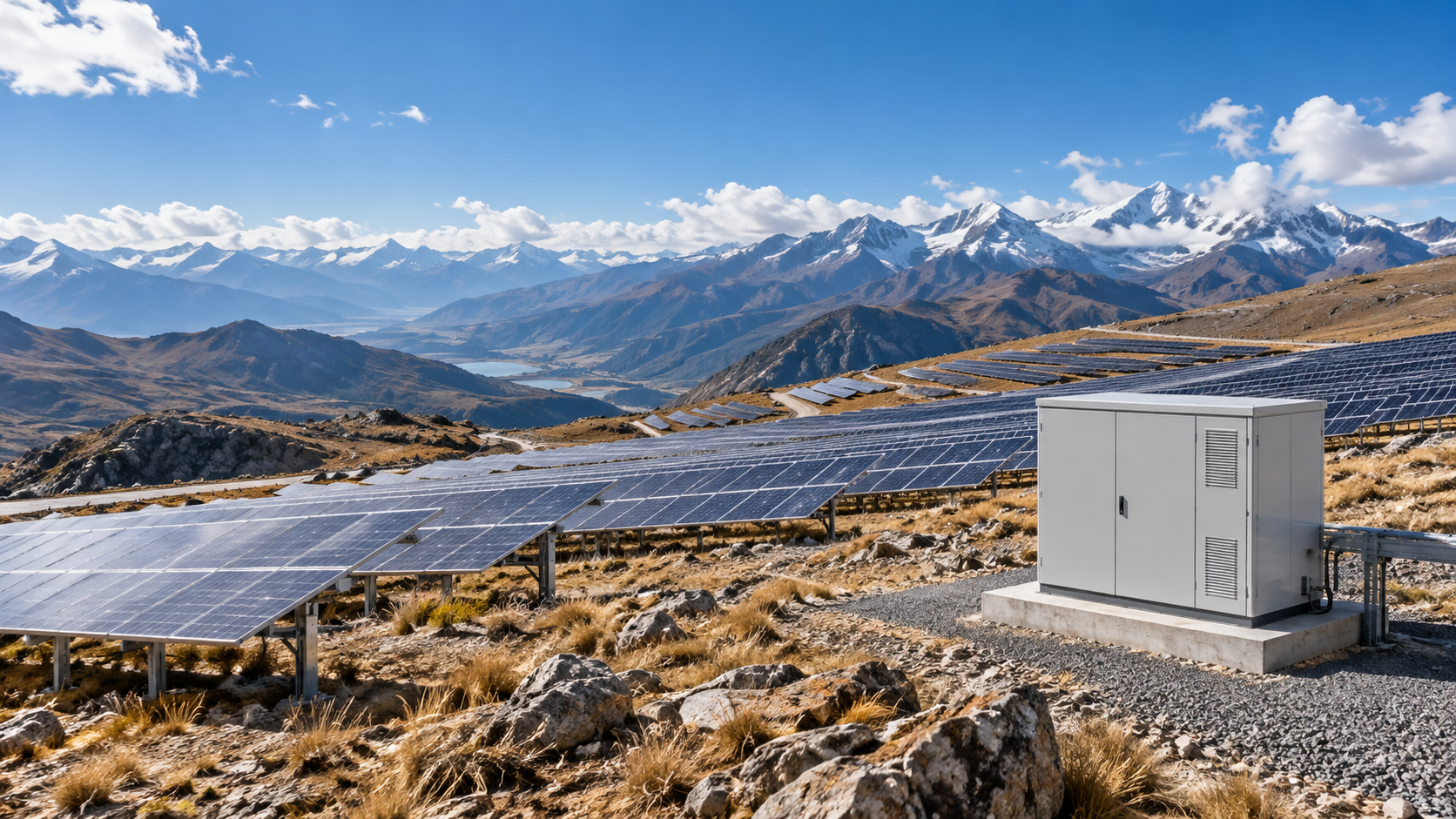
Declare the site elevation
Record the maximum project elevation and expected ambient conditions before selecting protection devices. Elevation can affect air insulation and cooling for some equipment, but the size and direction of any correction depend on the product, installation and manufacturer's declared limits.
IEC 60947-2:2024 applies to circuit-breakers within its stated voltage scope, including up to 1 500 V DC. It does not provide one universal correction factor for every device or an assembly-wide value for the complete combiner box. Request current product documentation for each selected breaker and switch.
- Use the actual site elevation and temperature basis.
- List every device whose ratings may depend on elevation.
- Keep product corrections separate from assembly verification.
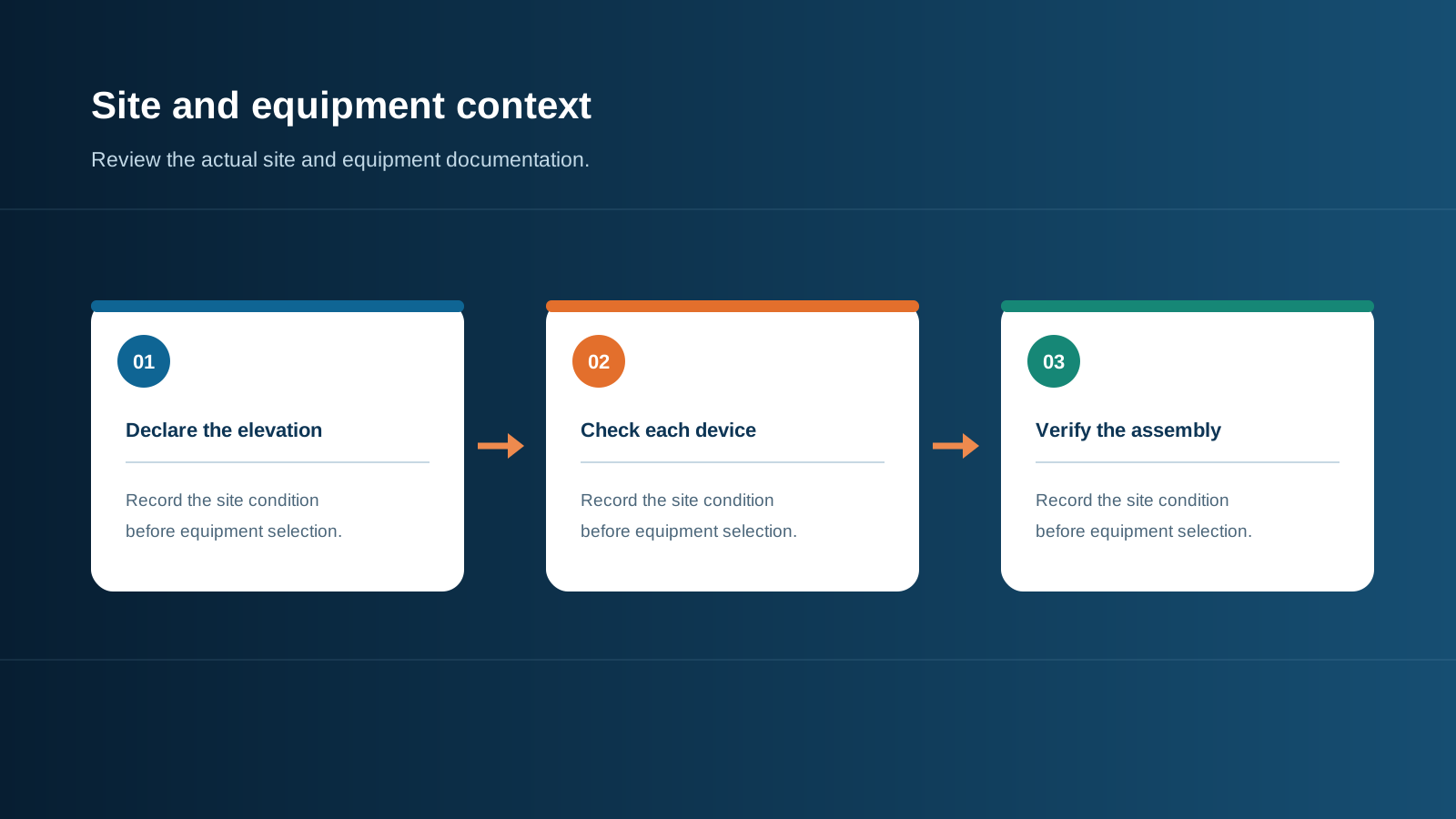
Technical diagram shown at a readable responsive scale.
Apply manufacturer corrections by device
A manufacturer's altitude table may adjust one or more characteristics, such as insulation voltage, operating voltage or current capacity. The table applies to the identified product family and conditions only. For example, Schneider Electric publishes a PowerPact B-Frame table with specific values at different elevations; those values must not be copied to another breaker, fuse, SPD or switch.
Record the exact part number, correction source, reference ambient, mounting and any coordination limits. If the selected component has no published data for the site condition, obtain written manufacturer confirmation or choose a documented alternative.
- Match each correction to its exact model and revision.
- Check voltage, current and breaking ratings independently.
- Retain supplier evidence with the project calculation.
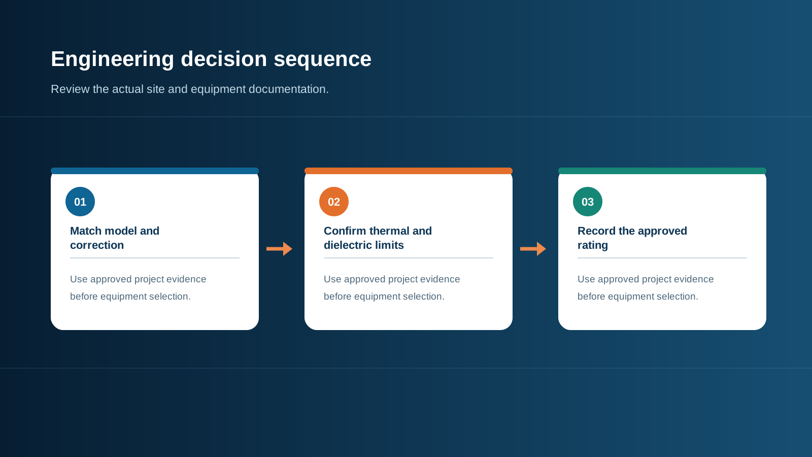
Technical diagram shown at a readable responsive scale.
Verify insulation and assembly coordination
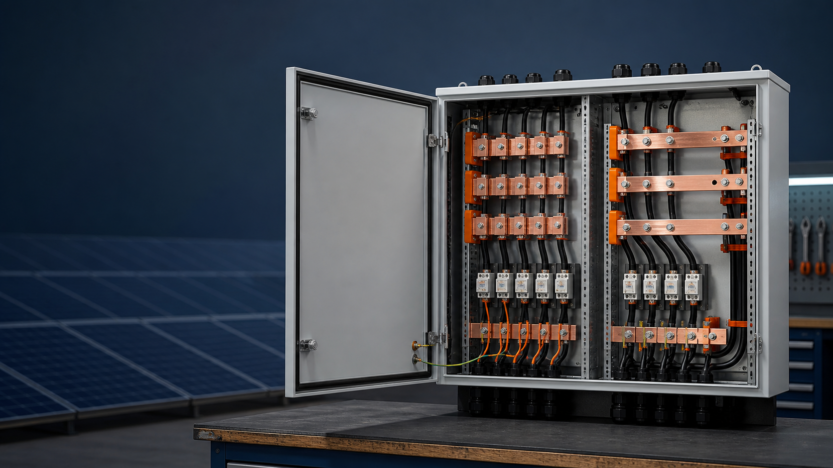
The complete DC path includes conductors, terminals, busbar supports, switching devices, protective barriers and the enclosure. Verify required insulation and clearances from the project design and applicable standards; do not claim that changing one clearance alone restores the rating of the whole assembly.
IEC 61439-2 defines requirements for power switchgear and controlgear assemblies, including assemblies for PV installations. Use the applicable assembly verification route and declared service conditions for the exact configuration.
- Review component working voltage and transient withstand together.
- Check spacing, barriers and insulation against the approved assembly design.
- Identify any special site condition requiring additional verification.
Technical diagram shown at a readable responsive scale.
Review thermal performance at elevation
Reduced air density can change cooling behavior for equipment that relies on convection. The effect depends on enclosure construction, ventilation, internal losses and component arrangement. Use component manuals and assembly design verification to confirm expected temperatures remain within declared operating ranges.
Avoid adding open ventilation solely to offset altitude; it may conflict with environmental protection requirements. If the supplier proposes a different enclosure, cooling method or load limit, capture that change in verified assembly documentation.
- Confirm design ambient and actual heat dissipation.
- Check thermal limits for the final mounted enclosure.
- Recheck protection and ingress requirements after a cooling change.
Coordinate PV voltage and protection
Calculate maximum DC voltage from the module string and project temperature assumptions, then verify every component against that value and expected fault conditions. The array design and the enclosure component ratings are related but are not interchangeable evidence.
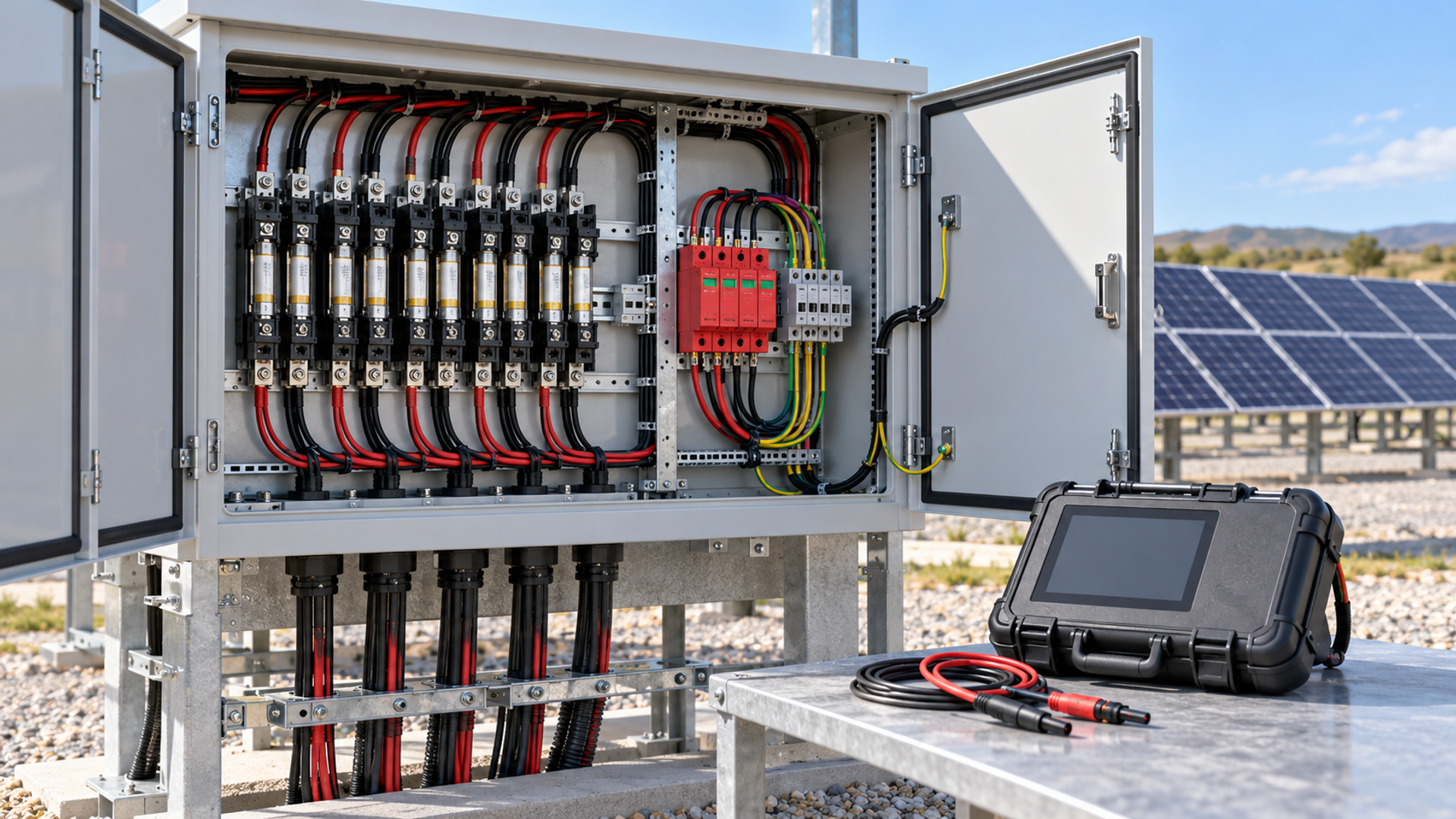
For surge protection, confirm device selection and coordination against the PV design, bonding arrangement and applicable current standard. Record whether an altitude limit or operating condition is specified by the SPD manufacturer; do not infer it from the rating of a nearby breaker.
- Use the approved array voltage and fault-current basis.
- Check each fuse, SPD, switch and terminal against its own data.
- Resolve rating mismatches before procurement or energization.
Document the site-specific rating
The procurement schedule should state declared elevation, ambient basis, maximum DC voltage, required current and expected supplier evidence. Ask for part-level correction tables and assembly-level verification supporting the delivered configuration.
At commissioning, compare nameplates and installed components with the approved schedule, retain inspection results and record deviations. Replacing a component later with a nominally similar part can invalidate an altitude-dependent assumption.
- Put the site elevation on the enquiry and equipment schedule.
- Retain approved part numbers, correction data and assembly evidence.
- Reassess before substituting a component.
General engineering information, not a project design, product certificate, code determination or safe-work procedure. Verify final ratings, installation, protection coordination and local requirements against current standards, exact manufacturer documentation and the approved project design.
Frequently asked questions
Is 2,000 m a universal threshold for PV combiner box derating?
No. Some product documentation uses a reference condition around that elevation, but the applicable limit and corrections are product-specific. Check each exact manufacturer's current instructions.
Does IEC 60947-2 provide one altitude factor for the entire combiner box?
No. It is a circuit-breaker product standard within a defined scope. The complete assembly needs its own design verification, and every component's ratings must be checked.
Can I use one breaker manufacturer's altitude table for other components?
No. Corrections apply to the listed product family and conditions. Obtain separate data for each fuse, SPD, switch and other device.
Why check thermal performance at altitude?
Air density and the final enclosure arrangement can affect heat transfer. Confirm component temperatures and assembly performance against the exact site and installation conditions.
What information should an altitude enquiry include?
Provide maximum site elevation, ambient conditions, system voltage, operating current, proposed component models and the assembly verification required for the project.
Review the project inputs
Share the system voltage, circuit schedule, installation location and site conditions so the equipment discussion can be checked against approved project documentation.
Discuss a projectContinue learning
Explore related technical guidance in Electrical Protection.
Prepared from the approved Period 09 source package with technical claims revised to retain project-specific and manufacturer-specific limits. Official source pages describe scope; they do not certify a NEUTRON product configuration or a customer installation.