
What an MC4 connector does
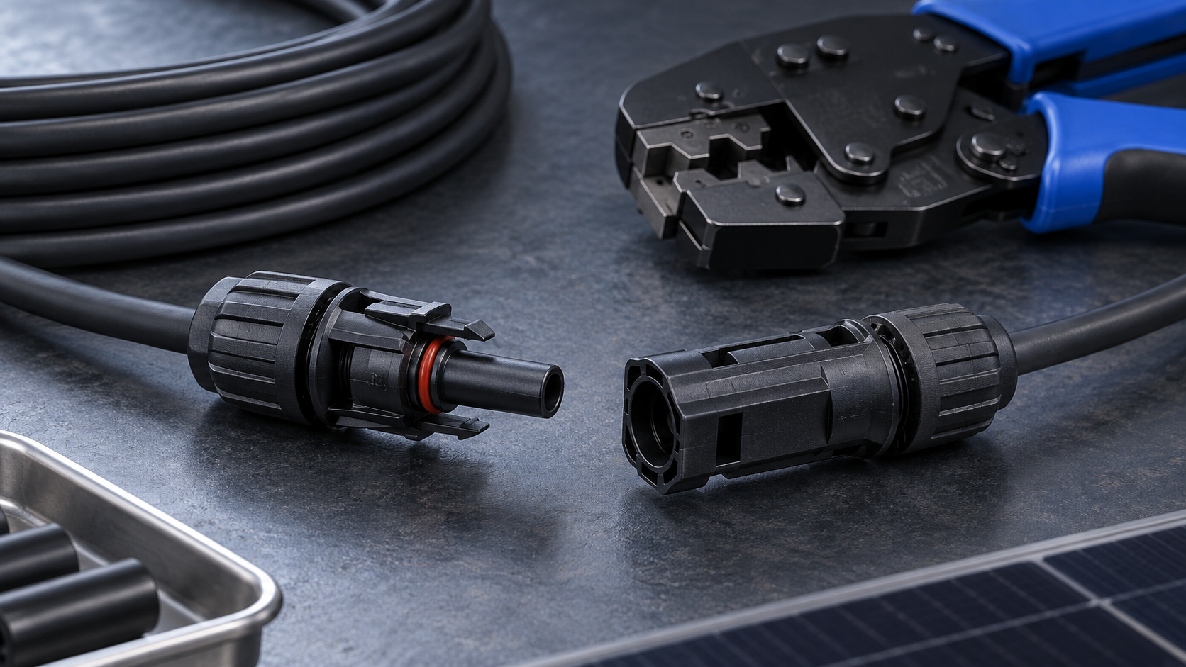
An MC4 connector is a weatherproof, touch-safe, single-pole direct-current coupler with a locking latch. One half is male, one female, and each pairs a crimped metal contact with a moulded insulating body and a compression gland that seals onto the cable jacket. The design lets an installer join modules and extend strings without tools while keeping live parts finger-safe.
Ratings for the common four-millimetre contact family typically reach 1000 V or 1500 V direct current with a continuous current capability of about 30 A to 45 A depending on contact design and cable cross-section. Ingress protection is normally IP68 when mated and IP2X when open, so an unmated connector left hanging on a roof is weather-exposed and should be capped.
Technical diagram shown at a readable responsive scale.
MC4 types and pin ratings
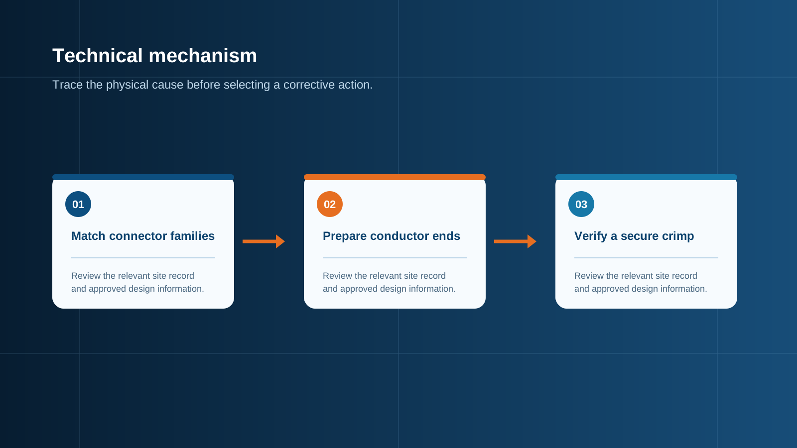
The name is used loosely across the market, and several variants share the same outward shape without being electrically identical. Confirm the following before ordering.
Temperature class matters as much as current. A connector rated to 85 °C in a rooftop cable tray behind a hot module is working close to its limit, and derating tables should be applied rather than ignored.
- Voltage class: 1000 V for most rooftop work, 1500 V for utility-scale strings; the insulating body and creepage geometry differ.
- Contact current rating, commonly 30 A, 39 A or 45 A, and the cable cross-sections each rating supports.
- Cable range of the gland, typically 4 mm² to 6 mm² for standard bodies, with separate parts for 10 mm².
- Contact metallurgy and plating, usually tin-plated or silver-plated copper; plating quality governs long-term contact resistance.
- Branch and Y variants for parallel connection, which must be rated for the summed current rather than the single-string current.
Genuine parts versus low-grade copies: what to watch
Visually identical connectors can differ enormously in construction. The failure mechanisms in low-grade copies are consistent and worth recognising: thin plating that wears through after a few mating cycles, springs with insufficient normal force, polymer bodies without proper ultraviolet stabilisation that chalk and crack within a few seasons, and glands that never achieve the claimed seal.
The practical defences are straightforward. Require certification evidence for the specific part number rather than the product family, verify the voltage and current rating printed on the body, buy male and female halves as a matched set, and keep one connector system across an entire array. Mixing dimensionally similar parts from different manufacturing origins is the single most common cause of high-resistance joints and eventual arcing.
Technical diagram shown at a readable responsive scale.
Crimping tools and proper termination
A correct crimp is a cold weld, not a squeeze. The contact barrel must be compressed to a defined profile that eliminates air gaps between strands, and only a die matched to the contact family achieves that. Pliers and general-purpose crimpers produce a joint that measures acceptable on day one and degrades steadily thereafter.
Cable choice belongs to this step. Photovoltaic cable is double-insulated, ultraviolet-resistant, halogen-free and rated to 90 °C or above at 1500 V; ordinary building wire in the same cross-section will not survive rooftop exposure and may not fit the gland correctly.
- Strip the cable to the length specified by the contact manufacturer, without nicking any strand.
- Do not tin the conductor; solder creeps under pressure and destroys the crimp over time.
- Use a ratcheting crimp tool with the correct die for the contact and cross-section, and complete the full ratchet cycle.
- Confirm insulation is not caught inside the barrel and that no strand sits outside it.
- Apply a pull test to the finished joint at the force stated by the contact manufacturer.
- Push the contact home until the retaining feature clicks, then tighten the gland nut with the specified spanner rather than by hand.
Matching connectors across a string
Every module arrives with factory-fitted connectors, and those set the standard for the rest of the string. Field-fitted extensions must mate with them mechanically and electrically, which means the same contact family, the same voltage class and the same or higher current rating.
Where two dimensionally similar but different systems are joined, the latch may click while the contact spring makes only partial engagement. The joint then carries full string current through a fraction of the intended contact area, heats, oxidises and eventually arcs. Since the fault is invisible from outside, the only reliable control is a documented single-system policy for the whole array.
Ingress protection and field reliability
A mated pair achieves its IP68 claim only when the gland is correctly tightened onto a cable within the stated diameter range and the latch is fully engaged. Unmated halves offer very little protection, so any spare connector must be fitted with a sealing cap rather than taped or left open.
- Support cable so that no mechanical load or bending moment is transferred to the connector body.
- Keep connectors out of standing water and off the roof surface, using clips or trays with an appropriate temperature rating.
- Allow a drip loop before the entry point so water runs away from the coupling rather than along the cable.
- Avoid repeated mating and unmating; each cycle wears the contact plating and lowers the normal force of the spring.
Connecting panels to the combiner box
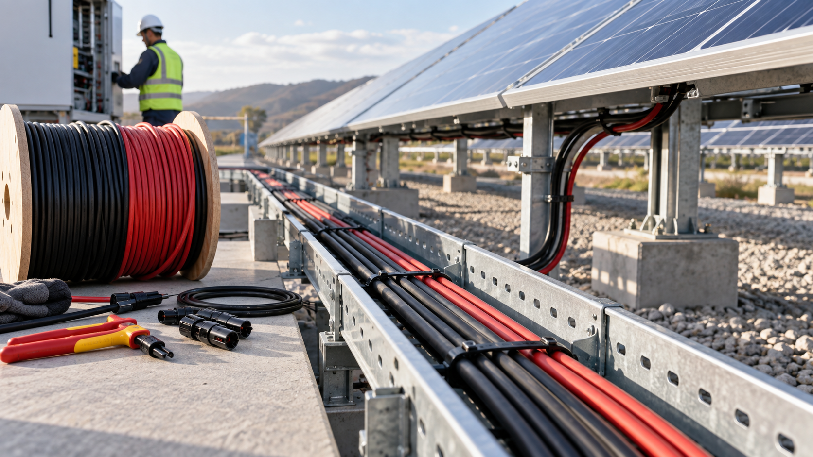
At the enclosure the string cables either terminate on connectors mounted through the gland plate or continue inside to a terminal block ahead of the string fuse. Both arrangements are valid, and both must maintain the voltage class of the array through the wall of the enclosure.
Where several strings are paralleled outside the enclosure with branch connectors, the combined current must remain within the branch connector rating and the arrangement must still allow each string to be individually protected. Paralleling upstream of the fuses defeats string-level protection and removes the fault discrimination the box is built to provide.
- Panel-mounted connectors must carry the same voltage and current rating as the string and the same ingress rating as the enclosure.
- Polarity must be verified before any string is presented to the box; a reversed string can damage protection devices and blocking components.
- Each positive string conductor lands on its own gPV fuse holder sized to string short-circuit current with the usual 1.25 factor.
- Internal conductor cross-section and busbar rating must carry the summed protected current continuously, not just intermittently.
- A direct-current isolator downstream of the collection busbar provides a safe working boundary for maintenance.
Inspection and torque checks
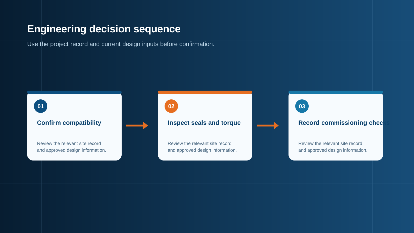
Commissioning should include a documented pass over every field-made joint: confirm the latch is engaged, confirm the gland is tight to the stated torque, and measure string open-circuit voltage and short-circuit current against the design calculation. A string reading low current with correct voltage usually indicates a high-resistance termination rather than a module problem.
Thermal imaging during a clear midday period is the most efficient periodic check. Any connector or fuse terminal noticeably hotter than its neighbours should be isolated, opened, inspected and re-terminated with a new contact. NEUTRON specifies the entry method, connector rating and internal protection of each combiner box against the string data supplied for the project.
This is general technical guidance. Confirm final ratings, protection coordination, installation and applicable local requirements against current standards, manufacturer documentation and the approved project design.
Frequently asked questions
Are all MC4 connectors compatible?
No. Many connectors share the outward shape and latch geometry without matching contact dimensions, spring force or plating. A latch that clicks does not guarantee full contact engagement, and a partially engaged joint carries full string current through a fraction of the intended contact area.
Can low-grade copies cause failures?
They are a leading cause of array faults. Typical defects include thin plating that wears through, weak contact springs, polymer bodies without ultraviolet stabilisation that crack within a few seasons, and glands that never reach the claimed seal.
Discuss your PV requirement
Share the system voltage, string arrangement, inverter interface and installation environment. NEUTRON can review the equipment configuration around your project documentation.
Discuss a projectContinue learning
Explore related technical guidance in Electrical Protection.

Published from the approved Period 06 source package. Technical values and final design decisions must be verified against the current applicable standard, manufacturer documentation and approved project design.