
1 What selectivity means
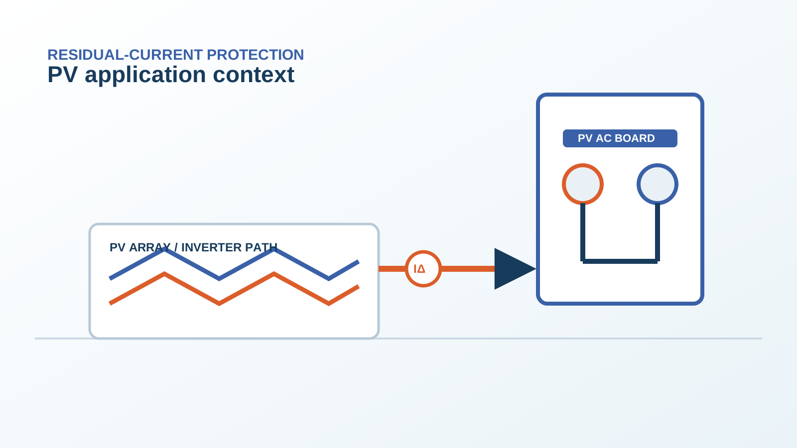
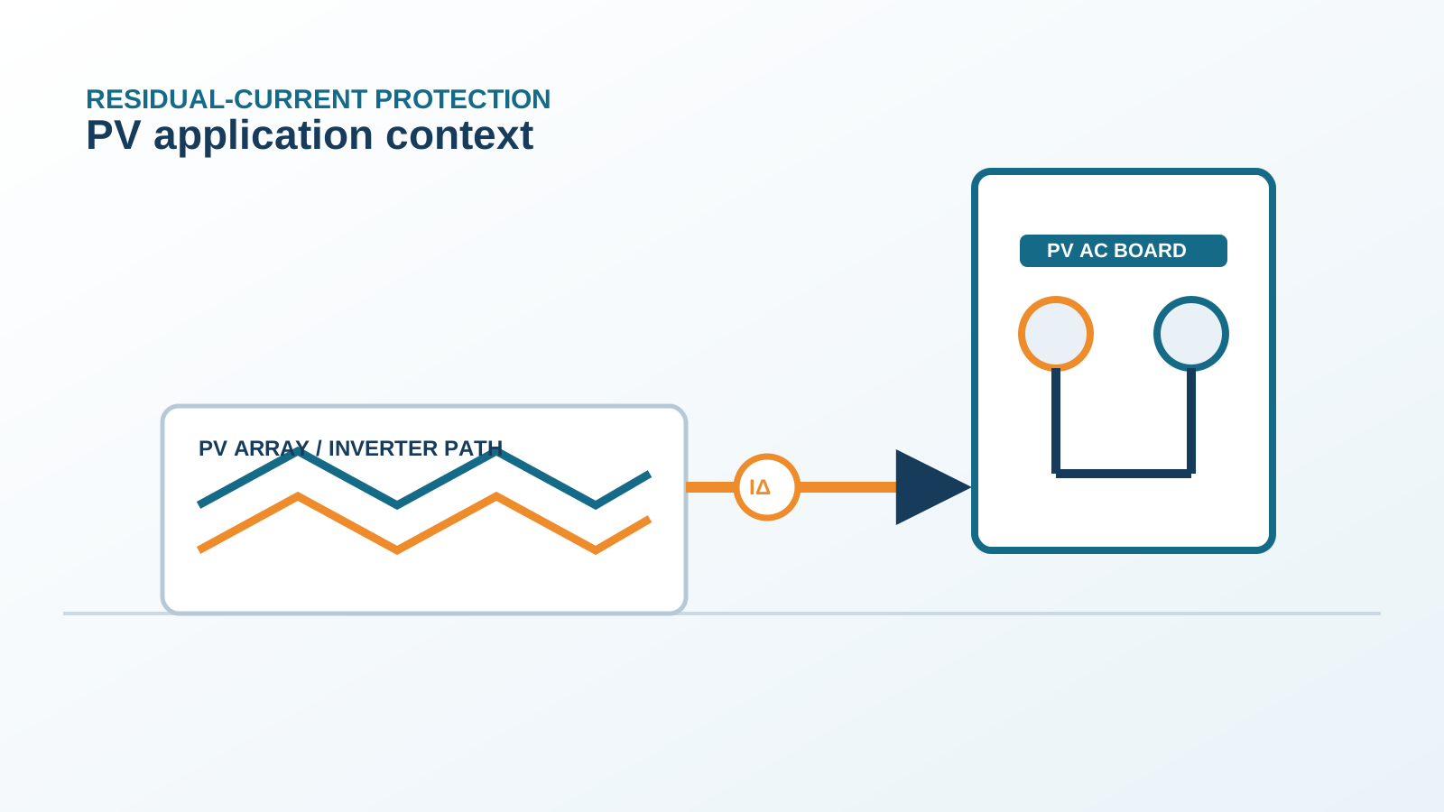
Selectivity (also called discrimination) means that when a fault occurs, only the protective device closest to the fault trips, leaving the rest of the installation energized. In a PV AC board this matters because an earth fault on one branch should not black out the whole array.
NEUTRON treats coordination as a design input, not an afterthought, when discussing PV protection schemes.
Technical diagram shown at a readable responsive scale.
2 RCCB+MCB as a pair
A common arrangement pairs a residual-current device (RCCB) with a separate miniature circuit breaker (MCB). The RCCB senses earth leakage, the MCB clears overload and short circuit. Together they cover the same branch that a single RCBO would, but as two separable units.
The advantage is that each device can be selected independently for its function.
3 Time-current coordination
Coordination is achieved by matching the time-current characteristics of the two devices so the downstream one acts first. The MCB must trip on overload before the upstream main, and the RCCB must clear the earth fault without being masked by the MCB's magnetic element.
Manufacturer coordination tables show which combinations give full selectivity.
4 Avoiding blinding of the RCD
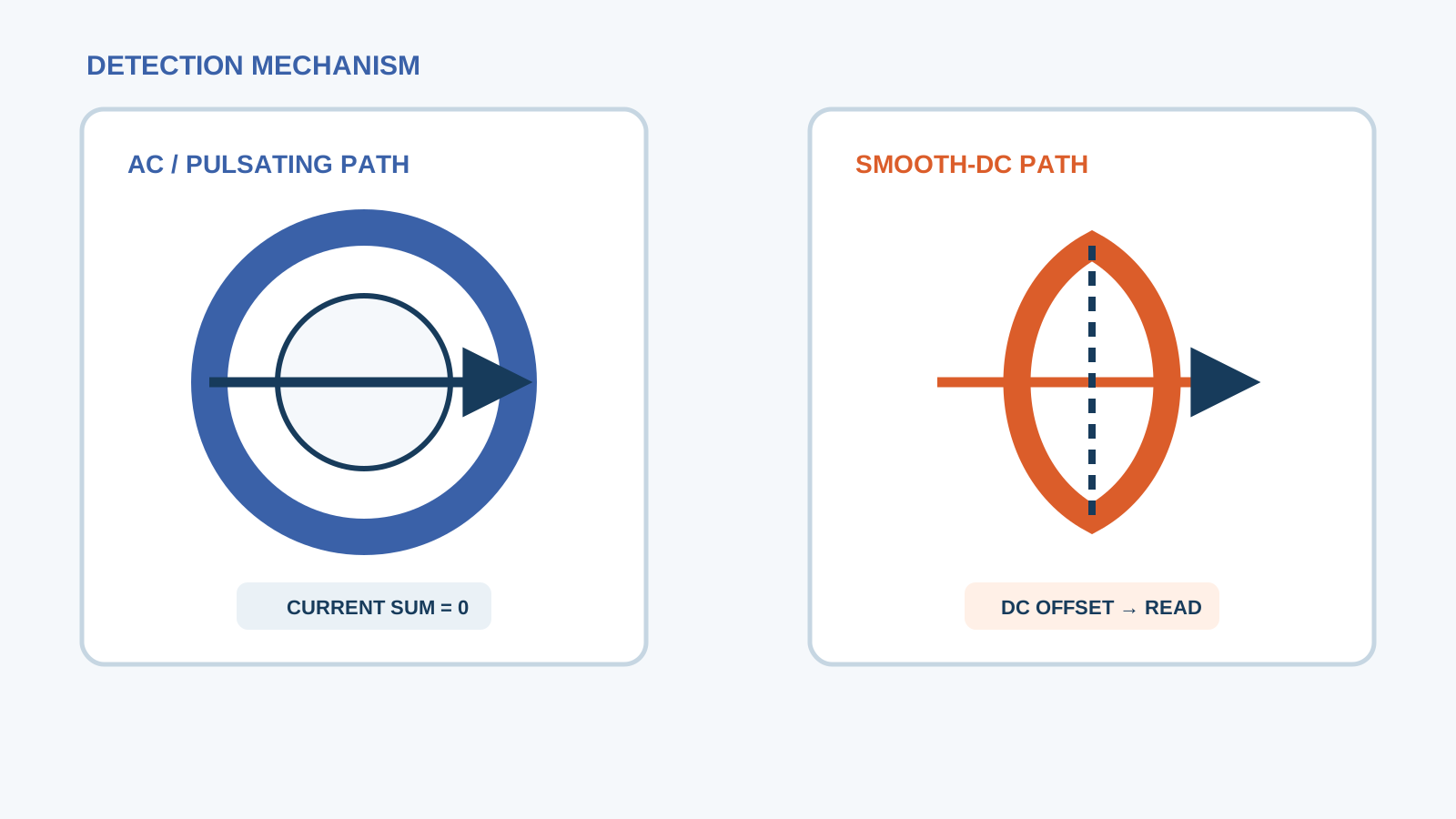
A residual-current device can be blinded if a solid fault holds the conductor at a fixed potential and no differential current flows through the toroid. Proper coordination keeps the MCB from clamping the fault in a way that removes the very residual current the RCCB must sense.
This is why the RCCB and MCB must be verified as a coordinated pair, not picked separately.
5 Upstream/downstream cascade
In larger PV AC boards a cascade runs from the main incomer, through a sub-distribution MCB, down to the branch RCCB+MCB. Each step must be current-limiting or time-delayed so that only the nearest device operates.
Cascade ratings are validated against the available fault current at each level.
6 PV AC board example
Consider a three-phase PV AC board: main switch, a 63 A distribution MCB, then per-branch 25 A MCBs each behind a 30 mA RCCB. With matched curves, a short circuit on branch three trips only the branch MCB, while an earth fault on branch three trips only that branch RCCB.
The other branches keep running.
7 Verification by chart
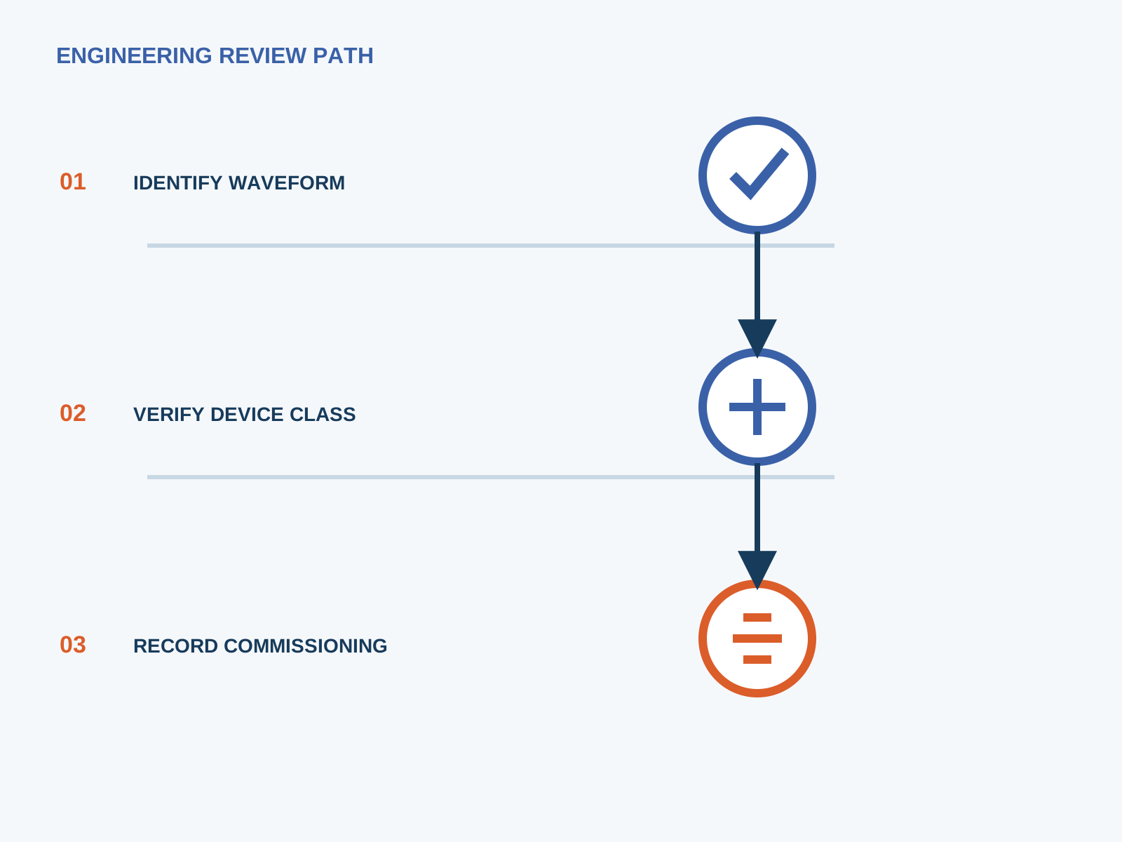
Use the manufacturer's selectivity chart to confirm that the branch MCB and the upstream MCB give partial or total selectivity at the relevant fault current. Where total selectivity is not achievable, accept partial selectivity only after the operator accepts the limited outage scope.
NEUTRON supplies coordination discussion material for this step.
8 Energy-limiting coordination
Energy-limiting devices cap the let-through energy during a fault, protecting downstream wiring and making coordination easier. When the upstream breaker is energy-limiting, even a fast branch MCB can be coordinated.
This is especially useful in compact PV AC boards where space limits device separation.
This is general application guidance. Confirm final ratings, trip settings, standards, inverter instructions and local installation requirements against approved project documentation and a qualified engineer's review.
Frequently asked questions
What is selectivity in PV protection?
Selectivity means only the device nearest the fault trips, so a branch fault does not shut down the whole PV AC board.
How to coordinate RCCB and MCB?
Match their time-current characteristics using the manufacturer coordination chart, keep the MCB from blinding the RCCB, and validate against the available fault current.
Why must RCD not be blinded?
If the MCB clamps a solid fault, no differential current reaches the RCCB toroid and earth leakage goes undetected. Coordination prevents this.
Is cascade allowed by standard?
Yes. Cascaded coordination is a recognized practice provided the combination is verified in the manufacturer's selectivity data and matches the site fault level.
Bring the protection inputs to the first review.
NEUTRON supplies coordination discussion material for this step.
Discuss a project requirementContinue learning
Explore related technical guidance in Electrical Protection.
Published from the approved period 10 source package; technical claims and source wording are retained for review.