
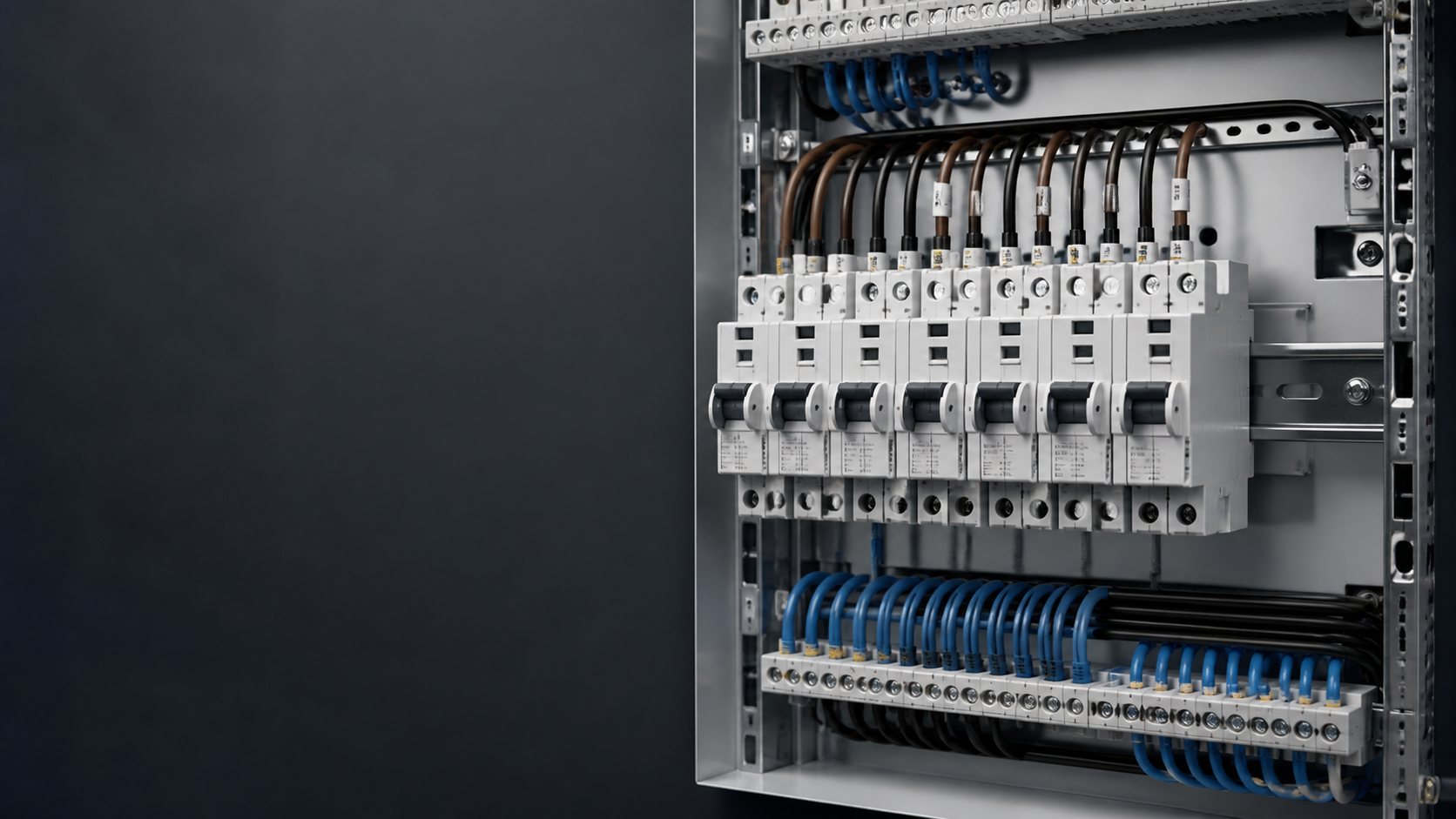
RCBO versus a separate RCCB and MCB
An RCBO to IEC 61009-1 combines residual current detection with overload and short-circuit protection in one device. An RCCB to IEC 61008-1 provides residual current protection only, and must always be backed by a separate overcurrent device.
The practical consequence is discrimination between final circuits. An RCCB protecting six circuits will disconnect all six when one develops an earth fault. One RCBO per circuit isolates the fault to the circuit that caused it, which is why commercial boards, rental properties and any installation with critical loads increasingly use RCBOs throughout.
- Fault isolation — only the faulty circuit disconnects.
- Simpler fault finding, because the tripped device identifies the circuit.
- No shared neutral bar confusion, since each RCBO carries its own neutral path.
- Higher device cost per way, offset by fewer callouts and less downtime.
- Width matters: a 1P+N RCBO in an 18 mm module lets you fit full protection into an existing board without replacing the enclosure.
Step one: choose the residual current type
The type letter describes which residual current waveforms the device can detect. IEC 61008-1 and IEC 61009-1 define Types AC and A; IEC 62423 defines Types F and B. Each type includes everything the previous one covers.
One rule saves a great deal of trouble: work from the load's power electronics, not from the circuit's nominal function. A "socket circuit" that will feed a portable EV charging cable is an EV charging circuit.
- Type AC — sinusoidal AC only. Suitable for purely resistive loads such as heating elements and incandescent lighting. Several national codes now restrict or prohibit it, because almost every modern load contains electronics.
- Type A — adds pulsating DC residual current from single-phase rectified loads. This is the sensible default for general socket outlets, lighting with electronic drivers, and most domestic and commercial final circuits.
- Type F — adds composite residual currents up to 1 kHz and tolerates a superimposed smooth DC component of up to 10 mA. Intended for single-phase frequency-controlled loads: heat pumps, inverter air conditioners, modern washing machines.
- Type B — adds smooth DC residual current detection across the range up to 1 kHz, with Type B+ extending to 20 kHz. Required where a load can produce smooth DC leakage, which in practice means EV charging, three-phase inverters, photovoltaic systems and variable frequency drives.
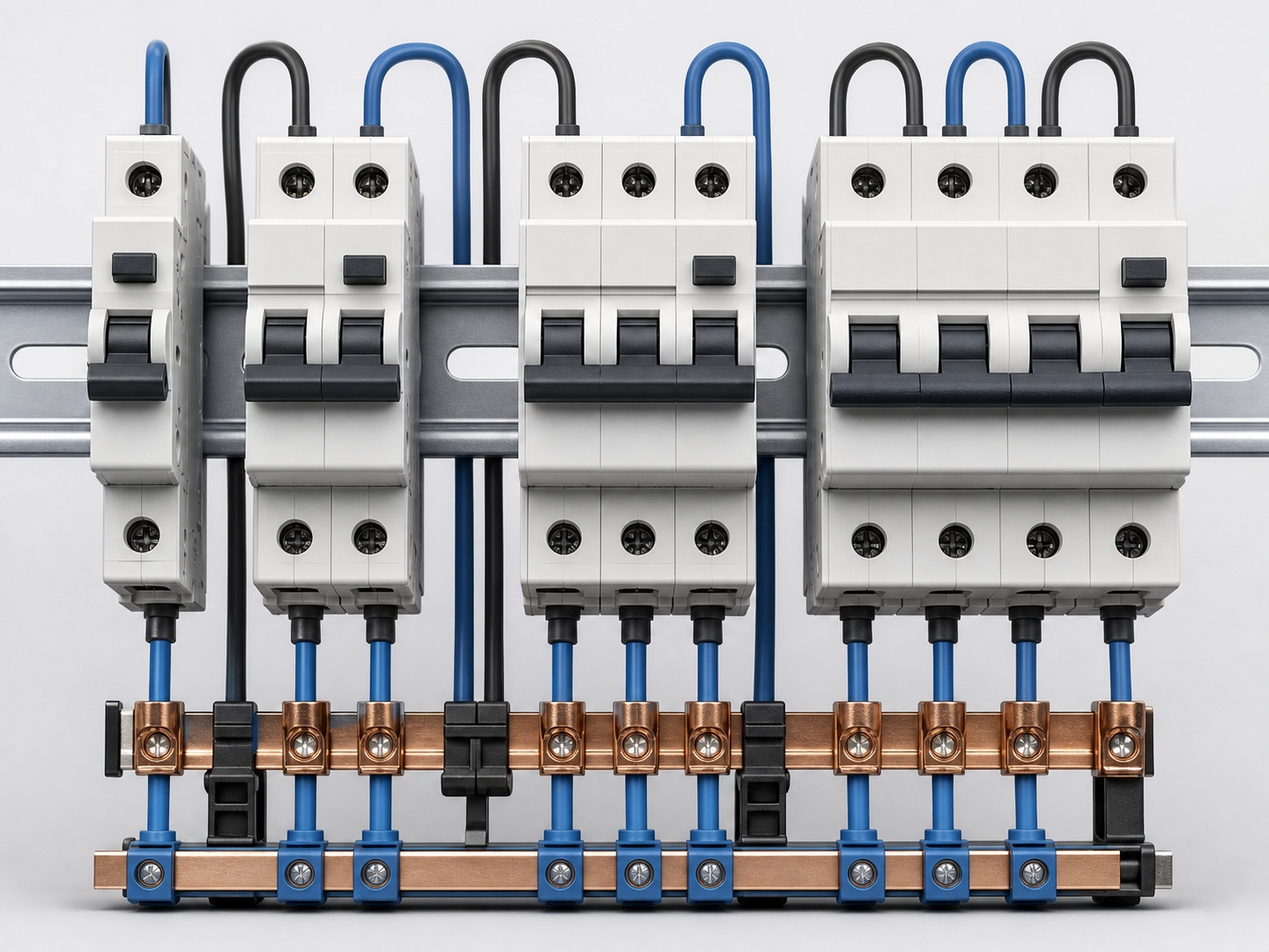
Step two: choose the rated residual current
The sensitivity IΔn determines what the device is protecting against, and it is not a case of "lower is safer".
Remember the standing leakage of the circuit itself. IEC 61008-1 and IEC 61009-1 permit a device to trip anywhere between 50% and 100% of IΔn, so a 30 mA device may operate at 15 mA. Filter capacitors in IT equipment, LED drivers and inverters each contribute a few milliamps; twelve devices on one circuit can approach the threshold before any fault exists. Split the load rather than raising the sensitivity.
- 10 mA — special applications only, such as medical locations and some laboratory circuits. Nuisance tripping is almost guaranteed on general circuits.
- 30 mA — additional protection against direct contact for socket outlets, portable equipment and locations containing a bath or shower. The default for final circuits.
- 100 mA — a compromise setting used for fire protection where 30 mA would cause unacceptable nuisance tripping.
- 300 mA — protection against fire caused by insulation faults, typically on the incomer or on distribution circuits, and used to obtain selectivity above 30 mA downstream devices.
- 500 mA and above — main incomer duty and industrial distribution, normally on an adjustable moulded case device rather than a modular RCBO.
Step three: rating, curve and breaking capacity
- Rated current In — 6 A, 10 A, 16 A, 20 A, 25 A, 32 A, 40 A, 50 A and 63 A are the standard values. Size to the cable, not to the load.
- Trip curve B — instantaneous trip between 3 and 5 times In. Use for resistive loads and long cable runs with low prospective fault current.
- Trip curve C — 5 to 10 times In. The general-purpose choice, suitable for mixed loads, socket circuits and small motors.
- Trip curve D — 10 to 20 times In. For high inrush loads such as transformers, capacitor banks and larger motor starters.
- Breaking capacity Icn — 6000 A is standard for domestic and light commercial boards; 10 000 A where the prospective fault current at the board is higher. Check the service short-circuit capacity Ics as well; a device with Ics equal to Icn remains fully serviceable after clearing a fault.
- Poles — 1P+N covers single-phase final circuits, 2P where both conductors must be isolated, 3P and 4P for three-phase loads.
Circuit-by-circuit selection table
Table — Typical RCBO selection by circuit type
| Circuit | RCD type | IΔn | Trip curve | Typical In | Note |
|---|---|---|---|---|---|
| General socket outlets | A | 30 mA | B or C | 16–20 A | Move to Type B if a portable EV cable will be used |
| Lighting with electronic drivers | A | 30 mA | B | 6–10 A | Watch cumulative driver leakage |
| Kitchen and utility appliances | A | 30 mA | C | 16–20 A | Separate high-leakage appliances |
| Heat pump / inverter HVAC | F | 30 mA | C or D | 20–32 A | Check the manufacturer's residual current declaration |
| Single-phase EV charging point | B | 30 mA | C | 32 A | Or Type A plus an RDC-DD to IEC 62955 |
| Three-phase EV charging point | B (4P) | 30 mA | C | 32 A | Four poles; one device per charging point |
| Solar PV inverter AC side | B | 30 mA | B or C | 16–32 A | Follow the inverter manual; transformerless units need Type B |
| Battery storage system | B | 30 mA | C | 32–63 A | Confirm the converter topology |
| Variable frequency drive | B | 100–300 mA | D | 25–63 A | Higher IΔn to tolerate filter leakage |
| IT and server room distribution | A or F | 100 mA | C | 20–32 A | Split circuits to manage cumulative leakage |
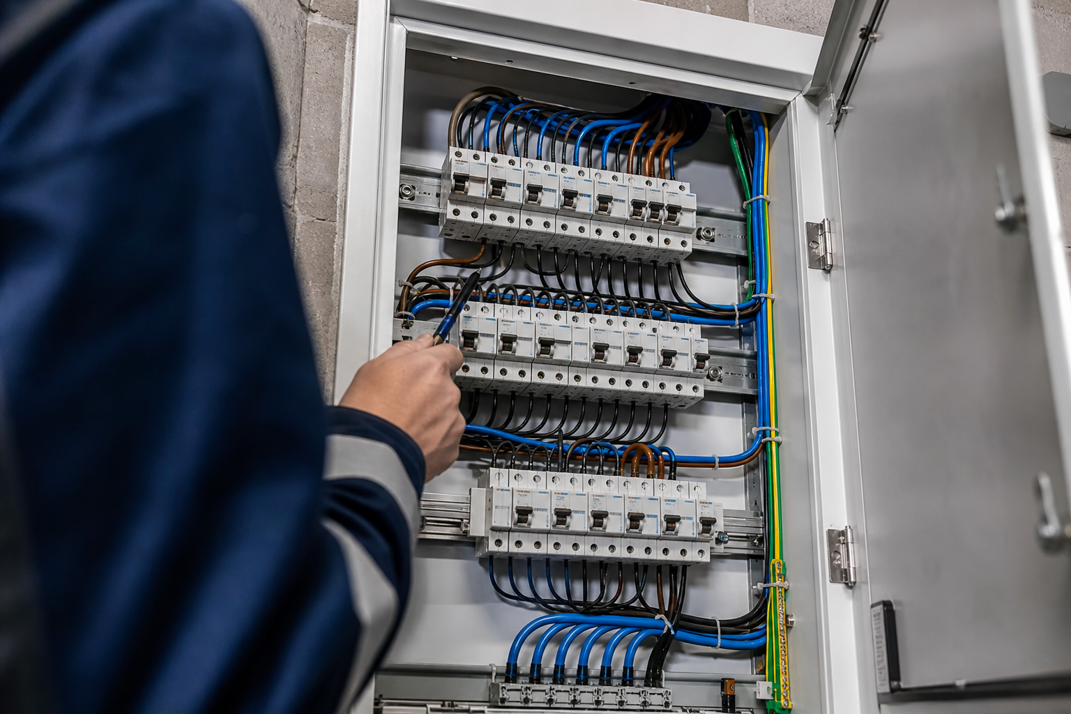
The NEUTRON residual current range
NEUTRON manufactures modular and moulded case residual current protection alongside the assemblies it goes into. The published ratings below come from the NEUTRON miniature circuit breaker and low-voltage distribution catalogues.
- WSB7L-63 residual current circuit breaker with overcurrent protection — 1P+N, rated currents 6 A to 63 A, rated residual operating current 30 mA, 100 mA or 300 mA, rated ultimate and service short-circuit breaking capacity both 6000 A, to IEC 61009-1. Published breaking times of 0.1 s at IΔn, 0.06 s at 2 IΔn and 0.04 s at 5 IΔn.
- WSB2L-32 line-plus-neutral leakage protection breaker — 230 V 50 Hz, 6 A to 32 A, 30 mA Type AC, C curve with 5–10 In instantaneous trip, 36 mm width, terminals for conductors up to 10 mm², to IEC 61009 and GB 16917.1. It interrupts both line and neutral and still provides leakage protection if line and neutral are transposed.
- DZ47LE-63 residual current operated circuit breaker — 230/400 V, frame ratings 40 A and 63 A, 1P, 2P, 3P, 3P+N and 4P configurations, to IEC 61009-1 and GB 16917.1.
- WCM30L moulded case residual current circuit breaker — 100 A, 225 A, 400 A and 800 A frames, adjustable residual settings of 30 mA to 500 mA, non-delayed operation below 0.1 s or adjustable delay steps of 0.2 s, 0.4 s and 0.8 s, ultimate breaking capacity 35 kA to 50 kA, to IEC 60947-2.
- WCM7EL electronic residual current breaker — LCD display of three-phase voltage, current and leakage, residual settings of 100 mA to 800 mA, 0.06 s delay type, configurable auto-reclosing between 20 and 60 seconds, for three-phase four-wire systems with a directly earthed neutral.
- Devices are supplied loose on 35 mm DIN rail or factory-fitted in NEUTRON GGD and GCS switchgear, XL-21 power distribution cabinets and metering cabinets built to IEC 61439-1 and IEC 61439-2.
Common selection errors
- Specifying Type AC because it is cheapest, on a circuit that feeds electronics.
- Assuming a 30 mA device solves everything. It does not provide fire protection at distribution level, and it does not detect smooth DC.
- Sizing the rated current to the connected load rather than to the cable, which leaves the cable unprotected under overload.
- Choosing a D curve to stop nuisance tripping caused by earth leakage. The curve affects overcurrent behaviour only.
- Ignoring Ics. A device that survives a fault but is no longer serviceable has to be replaced anyway.
- Sharing a neutral between two RCBOs, which produces immediate and baffling tripping.
- Forgetting the six-monthly test button routine, then finding a seized mechanism during an inspection.
This is general technical guidance. Confirm final ratings, protection coordination, standards, documentation and configuration against the approved project design and applicable local requirements.
Frequently asked questions
What type of RCBO is suitable for a circuit?
Choose the residual-current type from the load waveform, then confirm residual sensitivity, rated current, trip curve, breaking capacity and pole arrangement from the circuit design.
When might Type B RCBO protection be needed?
Some EV charging, PV, energy-storage and drive applications can require Type B protection or another manufacturer-approved residual-current arrangement. Confirm the equipment instructions and local rules.
Why can an RCBO trip without an obvious fault?
Cumulative leakage from electronic loads can approach the operating threshold. Investigate the actual leakage, neutral arrangement and circuit grouping before changing the protection device.
Bring the project inputs to the first review.
Share the circuit schedule, application details, operating conditions and destination-market requirements so the configuration can be reviewed before quotation.
Request a quoteContinue learning
Explore related technical guidance in Electrical Protection.

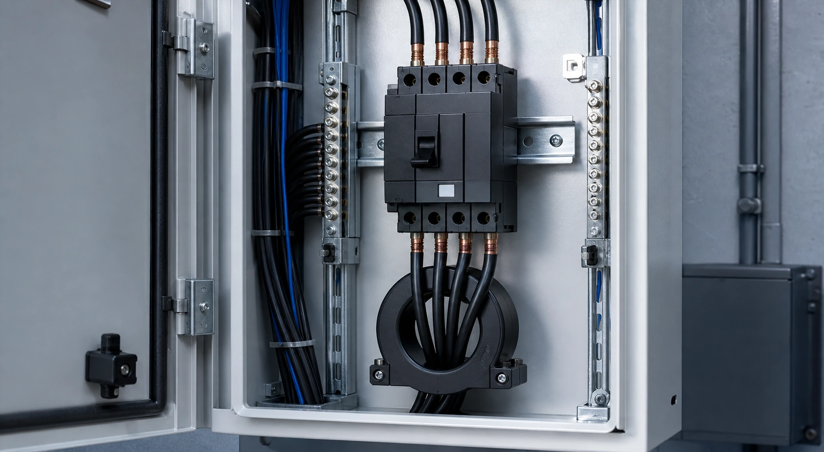
Source article retained from the approved NEUTRON publishing file. Final ratings, standards, product documents and project configuration must be confirmed against the applicable requirements.