
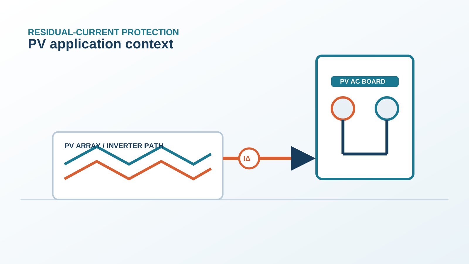
2. What an RCM measures on the DC side
A residual-current monitor placed on the grounded DC side measures the imbalance between the outgoing and returning currents of the array. In a healthy system those currents are equal; when insulation breaks down to earth on the unearthed conductor, the difference appears as a residual current that the sensor reports.
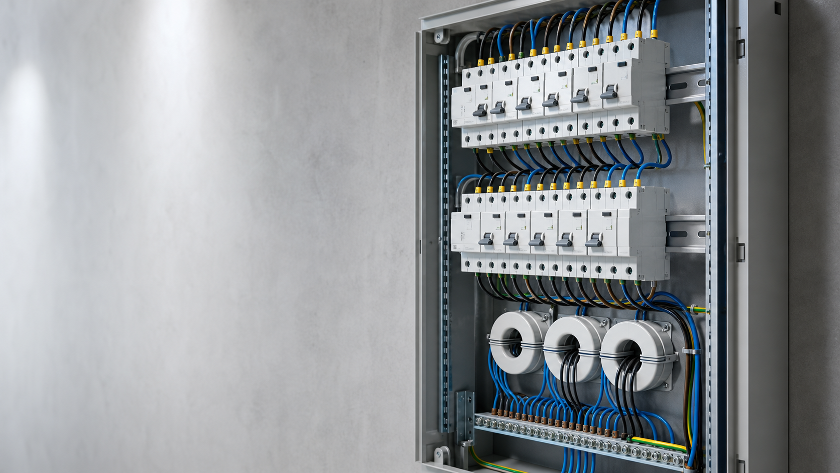
The RCM is a measuring and alarming device, distinct from a breaker that opens the circuit, and it can present a continuous reading rather than a single threshold state.
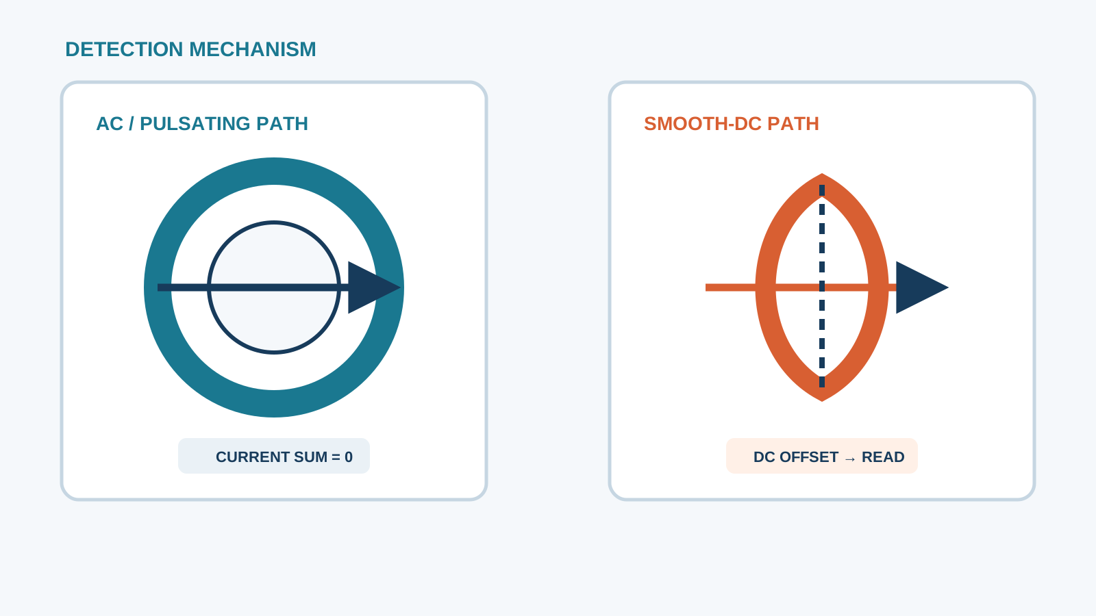
Technical diagram shown at a readable responsive scale.
3. Type-B-sensitive RCM threshold
Because PV faults can contain smooth direct current as well as alternating and pulsating components, a Type-B-sensitive monitor is required. Such a device responds to AC, pulsating DC and pure smooth DC down to the relevant detection band, commonly aligned with the 6 mA smooth-DC figure used for inverter leakage.
Setting the alarm below the protective threshold gives early warning before a trip-level fault develops, turning an imminent trip into a manageable maintenance task.
4. RCM vs RCD function
An RCD both senses and interrupts residual current, whereas an RCM only senses and reports. On the DC side a monitoring device is often preferred because it can log trends and raise staged alarms without disconnecting the array.
A separate protective device, or the inverter's own protection, then performs the disconnection when the current reaches the trip level, keeping generation available during investigation.
5. Where to place the RCM
The sensor is mounted on the combined DC conductor path at a point that sees the whole array current, usually at the combiner output or the inverter DC input. Placing it after the string fuses but before the inverter lets it observe the aggregate residual current and avoids masking by individual string behaviour.
Correct routing through the measuring core is essential, as a missed conductor would null the reading and hide a real fault.
6. Alarm and disconnection logic
The RCM issues a pre-alarm at a low residual level and a main alarm at the protective threshold. The system can be arranged to command an orderly shutdown through the DC coordination, or simply to notify operations for investigation.
The disconnection point is selected so that clearing the fault does not unnecessarily drop healthy strings and interrupt the rest of the plant.
7. Coordination with inverter monitor
Modern inverters embed their own residual-current supervision, and the external RCM should be coordinated with it rather than duplicating blindly. A sound arrangement uses the inverter as the primary fast trip and the external RCM as an independent back-up and trend logger.
NEUTRON supplies the DC-side protection and switchgear that interface with, but do not replace, the inverter's internal functions in this layered scheme.
8. Acceptance test
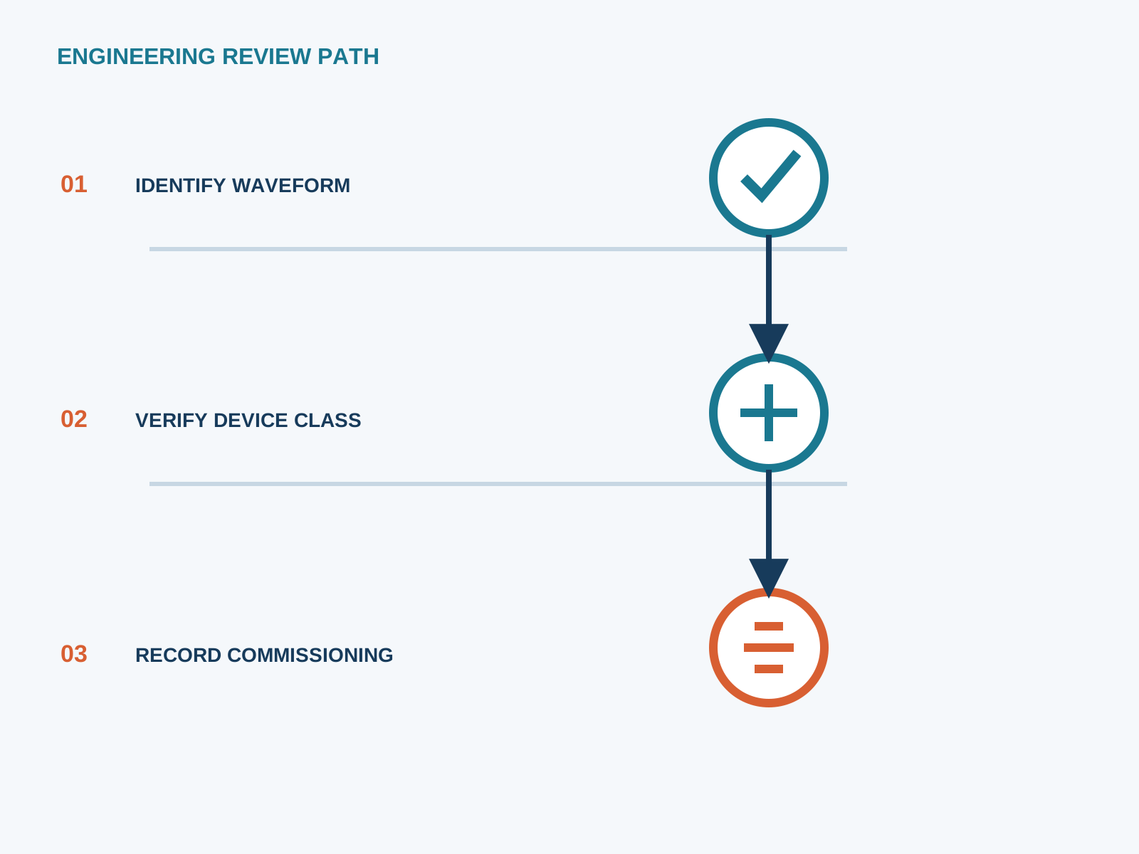
At acceptance the RCM is tested with a calibrated residual-current injection across its full frequency band, including a smooth-DC component, to confirm it reports at the set threshold. The alarm contacts and any shutdown command are exercised, and the results are filed with commissioning records.
Periodic re-testing keeps the monitor trustworthy as connectors age and the array environment changes.
This is general application guidance. Confirm final ratings, trip settings, standards, inverter instructions and local installation requirements against approved project documentation and a qualified engineer's review.
Frequently asked questions
What is RCM in a grounded PV array?
A residual-current monitor on the grounded DC side measures the imbalance between array outgoing and return currents and reports any residual current leaking to earth, providing early warning of insulation breakdown.
RCM or RCD for grounded PV?
An RCM reports and logs; an RCD reports and interrupts. Many grounded PV designs use an RCM for trend monitoring and rely on the inverter or a Type-B RCD for disconnection. The choice depends on whether automatic opening is required at that point.
What sensitivity is needed?
The monitor should be Type-B-sensitive, responding to AC, pulsating DC and smooth DC, with an alarm set in line with the protective threshold, commonly referenced to the 6 mA smooth-DC level used for PV leakage.
Where is the RCM installed?
At the combiner output or inverter DC input where it can observe the total array current through its measuring core, after the string fuses and before the inverter.
Bring the protection inputs to the first review.
{ "@context":"https://schema.org", "@type":"Article", "headline":"Residual-Current Monitor for Grounded PV Arrays (RCM)", "author":{ "@type":"Organization", "name":"NEUTRON LLC" }, "publisher":{ "@type":"Organization", "name":"NEUTRON LLC", "logo":{ "@type":"ImageObject", "url":"https://www.neutronele.com/logo.png" } }, "datePublished":"2026-09-03", "dateModified":"2026-09-03", "mainEntityOfPage":"https://www.neutronele.com/insights/rcm-residual-current-monitor-grounded-pv-array", "image":"https://www.neutronele.com/insights/img/rcm-residual-current-monitor-grounded-pv-array-hero.jpg" }
Discuss a project requirementContinue learning
Explore related technical guidance in Electrical Protection.

Published from the approved period 10 source package; technical claims and source wording are retained for review.