
2. Role of IMD per IEC 61557-8
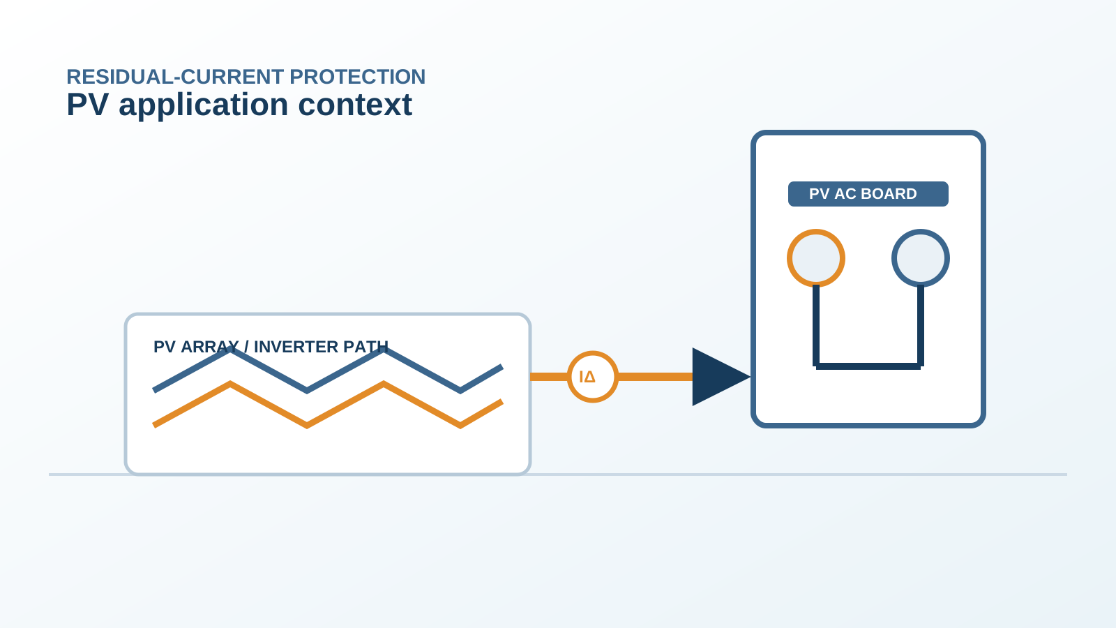
IEC 61557-8 defines the functional requirements for insulation monitoring devices used on unearthed or high-resistance-earthed systems. An IMD installed on the PV DC side continuously evaluates the insulation resistance between the array conductors and earth. Where that resistance falls below a preset limit, the device raises an alarm so operators can locate and clear the degraded string before a second fault creates a hazardous condition.
The standard also addresses the measuring principle and the response behaviour, giving specifiers a consistent basis to compare devices and to set thresholds that match the project's earthing philosophy.
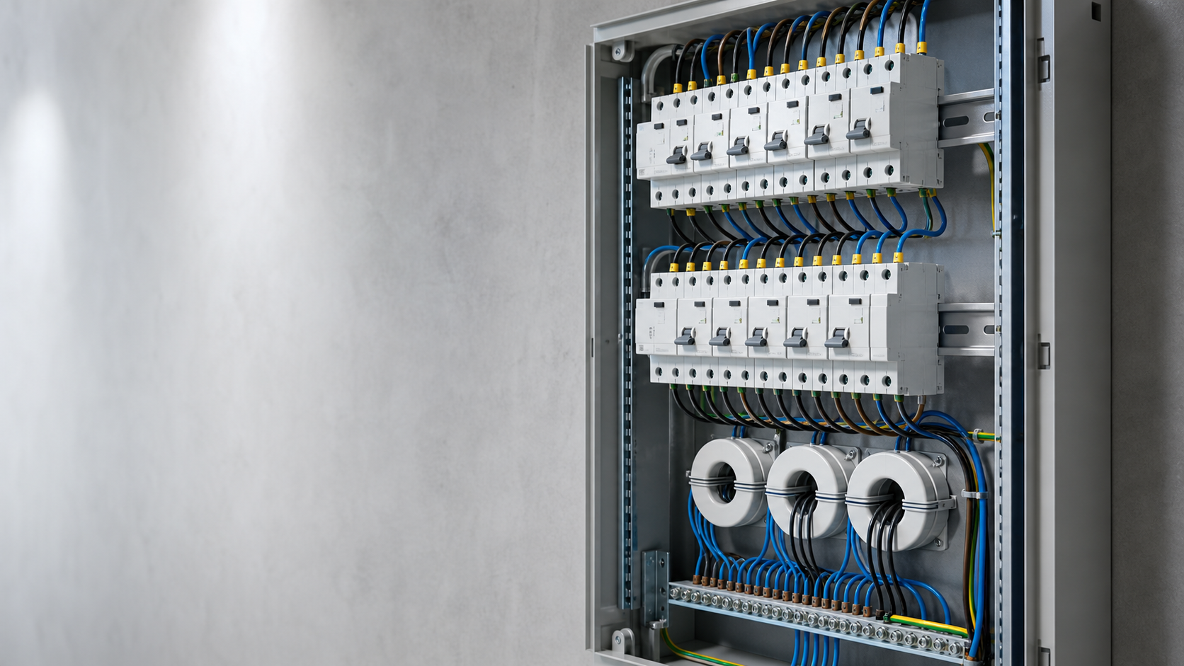
Technical diagram shown at a readable responsive scale.
3. How IMD measures array insulation
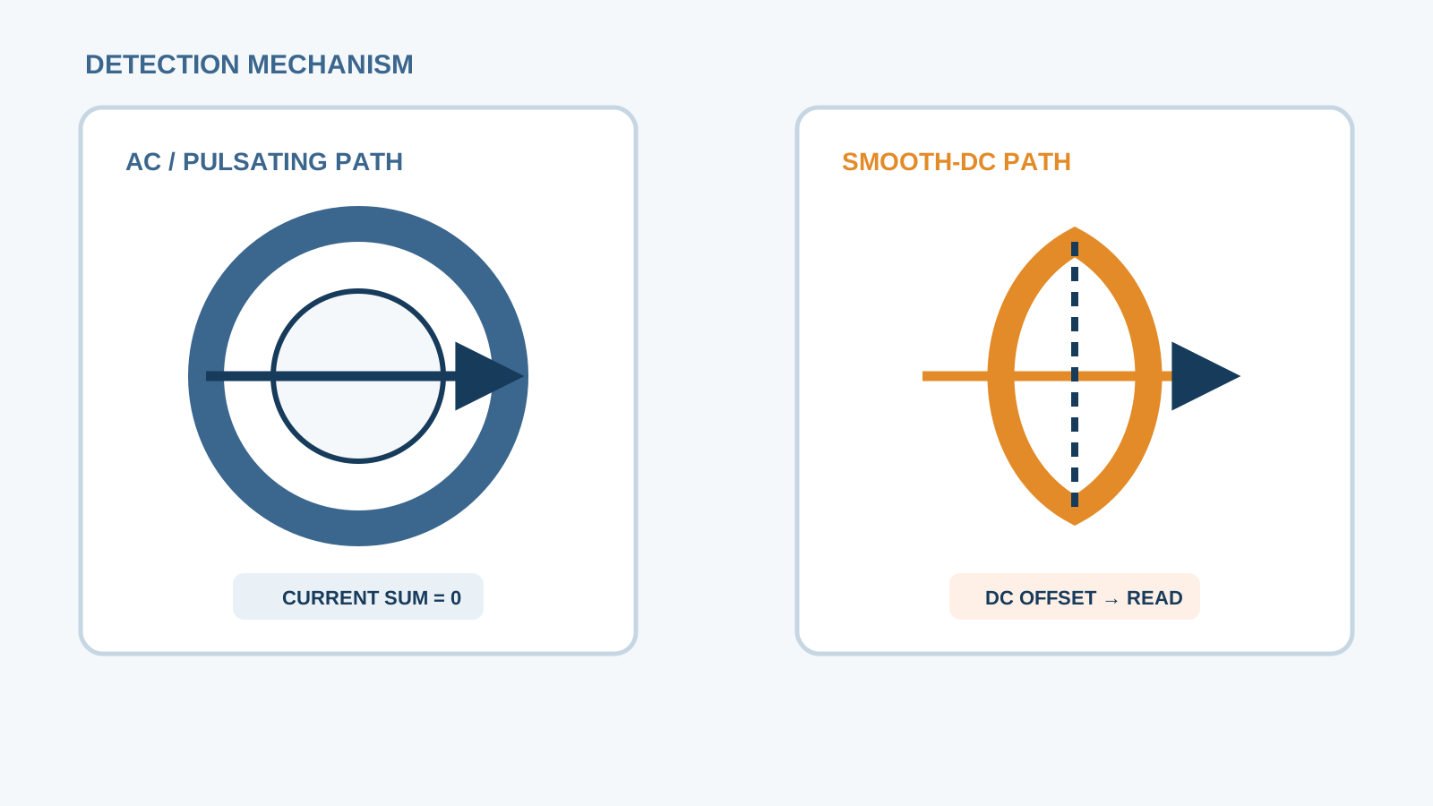
The monitor injects a supervised measuring voltage between the DC conductors and earth through an internal bridge network and observes the resulting leakage path. By comparing the two conductor-to-earth branches it derives the equivalent insulation resistance and, in more capable units, can indicate which polarity is closer to earth.
The injected signal is small enough to avoid disturbing array operation, and the measurement runs whether the inverter is producing or idle, so the baseline is always available for comparison.
4. Alarm thresholds and trip logic
Most PV IMDs are configured with a resistance alarm threshold, frequently set around a few kilo-ohms per installed volt class, plus an optional pre-alarm band. Because a single fault on an ungrounded array is not itself dangerous, the usual response is an alarm rather than an immediate trip.
The design can however command an orderly disconnect through the protection coordinator if a fault persists or if the insulation resistance collapses toward a short, keeping the response proportionate to the actual risk.
5. IMD vs RCD on the DC side
A residual-current device senses differential current in a closed loop and trips to clear it, which suits earthed systems where a fault current actually flows. On an ungrounded array the first fault carries essentially no current, so an RCD has nothing to detect.
The IMD is the appropriate primary monitor for the ungrounded DC side, while a Type-B-sensitive RCD remains relevant on the earthed AC side where smooth-DC leakage from the inverter must be interrupted.
6. Floating array fault location
When the IMD reports low insulation, the next task is to identify the affected string. Because the array floats, the fault current is negligible, so location relies on isolating sections and re-measuring, or on a monitor that can compare per-string leakage.
NEUTRON supplies DC protection and coordination hardware that supports staged isolation, but the faulted module or connector is found by sectional disconnection during a controlled maintenance window.
7. Commissioning the IMD
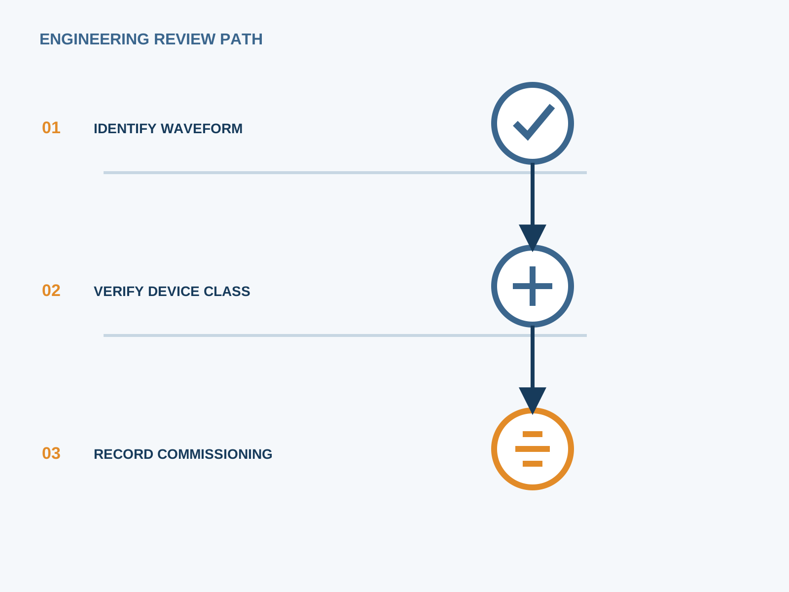
At commissioning the monitor is energised, its measurement bridge is verified, and the alarm thresholds are set to the project value. A deliberate high-resistance test to earth confirms the device responds, and the result is recorded in the handover file.
The IMD should be checked after any array extension, since added strings change the total capacitance and the balance of the two earth branches.
8. Limits of IMD alone
An IMD gives early warning but does not by itself remove a fault or protect against the consequences of a second, opposing fault. A complete scheme pairs the monitor with coordinated DC isolation, string fusing or string breakers, and an AC-side residual-current device.
NEUTRON provides the DC protection and low-voltage switchgear components that complete this chain; the inverter and battery inputs are supplied by other parties in the project.
This is general application guidance. Confirm final ratings, trip settings, standards, inverter instructions and local installation requirements against approved project documentation and a qualified engineer's review.
Frequently asked questions
What is an IMD in a PV system?
An insulation monitoring device is a continuous monitor fitted to the DC array that measures the insulation resistance between the PV conductors and earth, raising an alarm when that resistance drops below a set limit. It is the standard way to supervise an ungrounded PV system per IEC 61557-8.
Is IMD required for ungrounded PV?
Where an array is deliberately left ungrounded, continuous insulation monitoring is the accepted method of supervision because a residual-current device cannot detect the first fault. Many grid codes and EPC specifications therefore call for an IMD on the ungrounded DC side.
Does IMD replace the RCD?
No. The IMD watches the ungrounded DC side where a first fault carries no current, while a Type-B-sensitive RCD protects the earthed AC side against smooth-DC leakage from the inverter. They cover different parts of the system and are complementary.
How does IMD find a ground fault?
The monitor detects that the insulation resistance to earth has fallen and can indicate which polarity is affected. Locating the exact string or module is then done by sectional isolation and re-measurement, sometimes with per-string monitoring, during a planned maintenance action.
Bring the protection inputs to the first review.
{ "@context":"https://schema.org", "@type":"Article", "headline":"Insulation Monitoring Device for Ungrounded PV Arrays", "author":{ "@type":"Organization", "name":"NEUTRON LLC" }, "publisher":{ "@type":"Organization", "name":"NEUTRON LLC", "logo":{ "@type":"ImageObject", "url":"https://www.neutronele.com/logo.png" } }, "datePublished":"2026-09-03", "dateModified":"2026-09-03", "mainEntityOfPage":"https://www.neutronele.com/insights/imd-insulation-monitor-ungrounded-pv-array", "image":"https://www.neutronele.com/insights/img/imd-insulation-monitor-ungrounded-pv-array-hero.jpg" }
Discuss a project requirementContinue learning
Explore related technical guidance in Electrical Protection.

Published from the approved period 10 source package; technical claims and source wording are retained for review.