
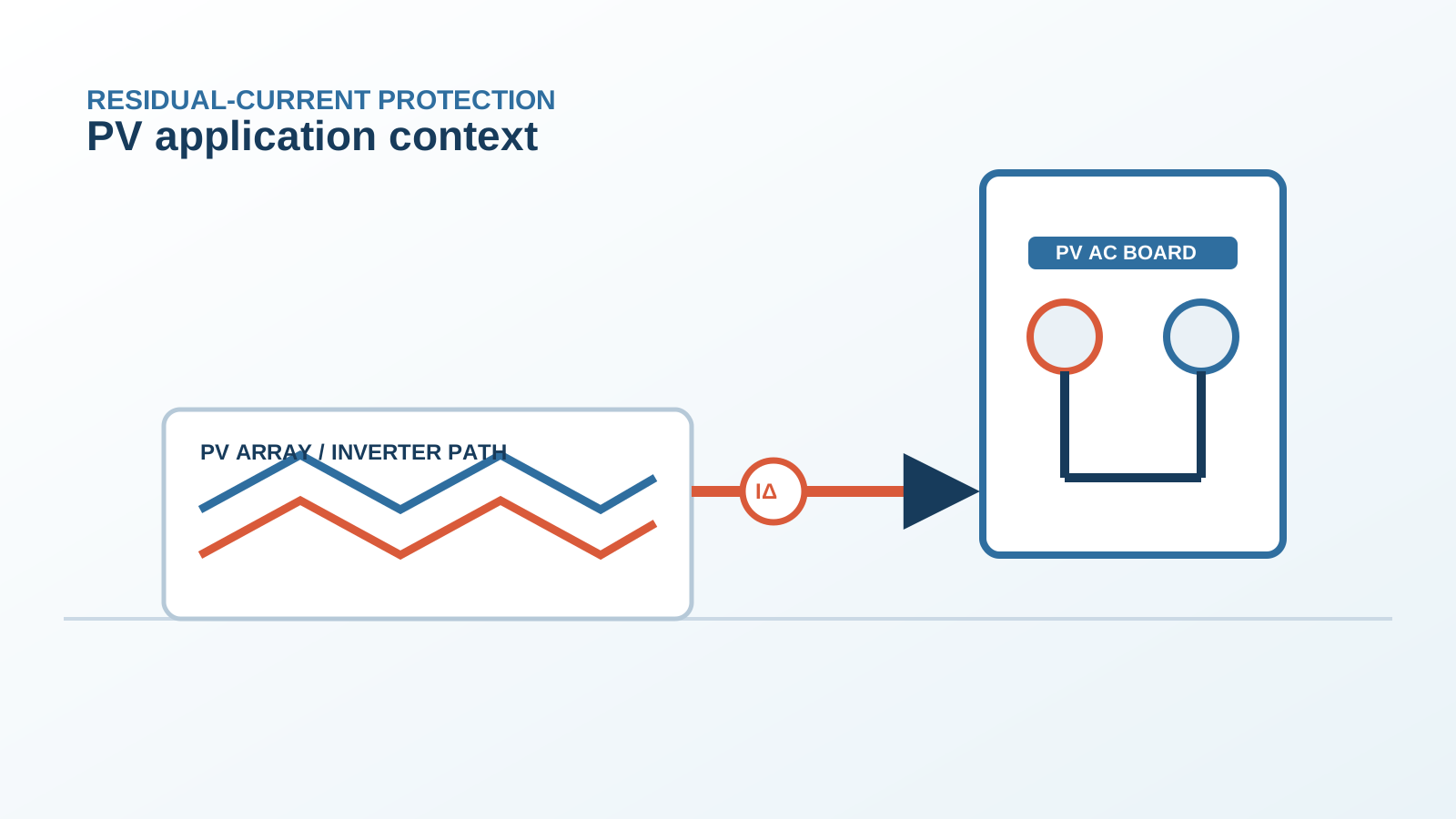
1. Where smooth DC leakage comes from
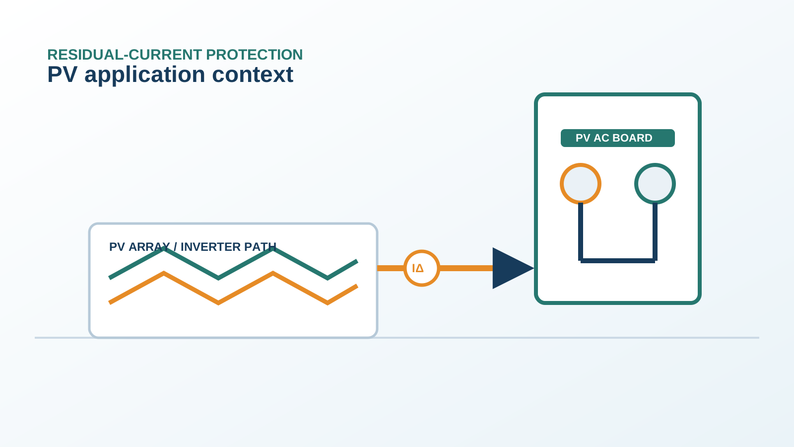
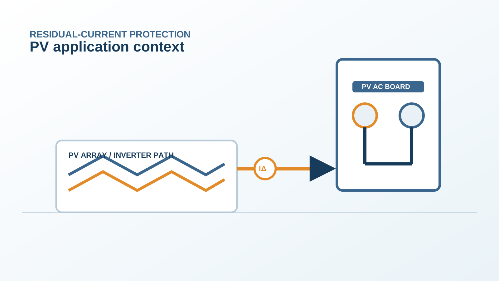
A transformerless inverter has no galvanic isolation, so a small smooth (pure) DC residual current can flow from the DC side to the AC side through the inverter internal capacitance and leakage paths. This smooth DC component does not exist in a normal grid-fed AC load.
Technical diagram shown at a readable responsive scale.
2. Why an AC-rated RCD ignores it
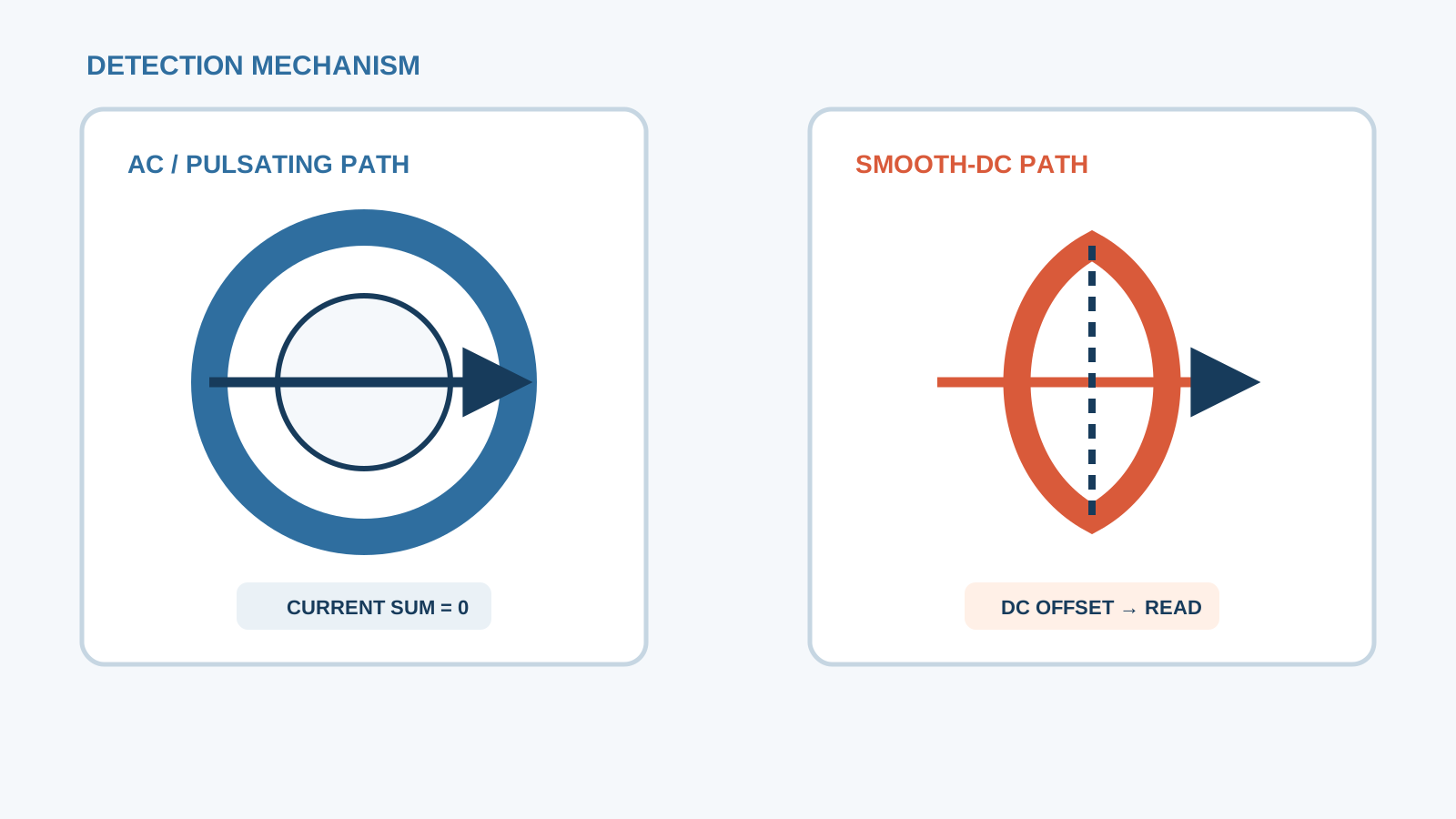
A Type A or AC RCD is built around a toroidal core that senses alternating flux. A steady DC component biases the core into saturation, where it loses sensitivity and does not respond to smooth DC. The leakage passes unseen, defeating the protection.
3. The real threshold that trips
In practice a PV RCD trips on smooth DC only when the leakage exceeds the device smooth-DC detection rating. For an all-current-sensitive device this is around 6 mA; below that the device tolerates the leakage, above it the device opens. The trip point is set by the device class, not by the array.
4. Type B trip on smooth DC
A Type B (all-current-sensitive) RCD detects AC, pulsating DC and smooth DC. When the smooth-DC leakage from the inverter and array crosses its threshold, it trips, which is the correct, safe behaviour rather than a nuisance event.
5. Accumulation across strings
Each string contributes its own small leakage. As more strings are paralleled in a combiner and fed to one board, the summed smooth-DC leakage rises. A board serving many strings reaches the trip threshold sooner than a single-string circuit.
6. Measuring DC leakage
Measure the smooth-DC residual with a meter that resolves direct current on the protective conductor, or read the inverter internal residual-current monitor log. Comparing the measured value with the device threshold shows how close the installation runs to tripping.
7. Setting versus reality
Specifying a device by its AC rating alone hides the smooth-DC risk. The real-world trip depends on the summed DC leakage, so the selection must be made on the all-current-sensitive characteristic, confirmed against the inverter declared leakage.
8. Fix hierarchy
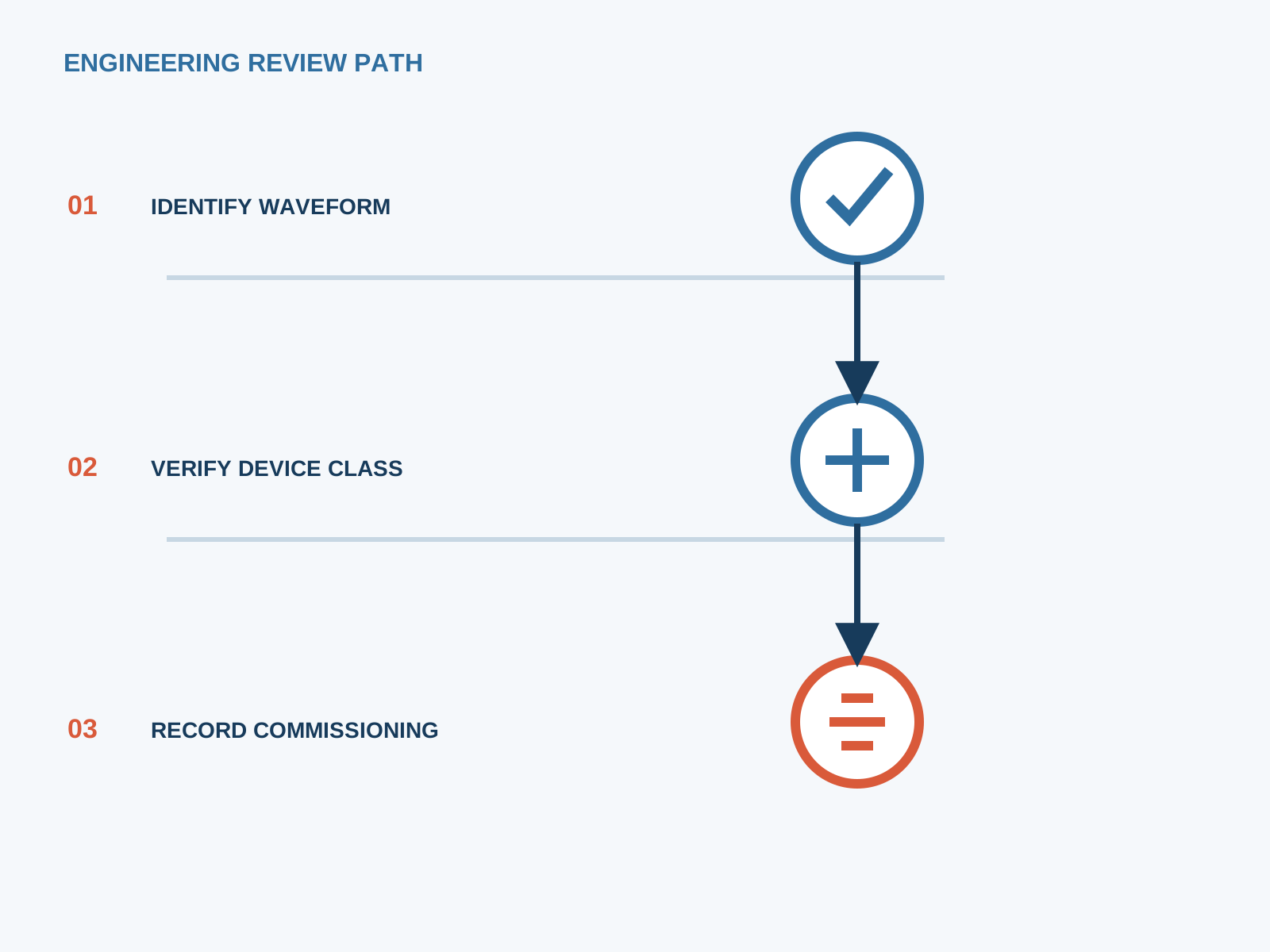
First confirm the device class, then reduce per-string leakage by good DC insulation and earthing, then coordinate the external Type B with the inverter monitor. NEUTRON supplies DC protection and low-voltage switchgear that match this hierarchy; the inverter is provided by others.
This is general application guidance. Confirm final ratings, trip settings, standards, inverter instructions and local installation requirements against approved project documentation and a qualified engineer's review.
Bring the protection inputs to the first review.
First confirm the device class, then reduce per-string leakage by good DC insulation and earthing, then coordinate the external Type B with the inverter monitor. NEUTRON supplies DC protection and low-voltage switchgear that match this hierarchy; the inverter is provided by others.
Discuss a project requirementContinue learning
Explore related technical guidance in Electrical Protection.
Published from the approved period 10 source package; technical claims and source wording are retained for review.