
1. What a neutral-ground loop is
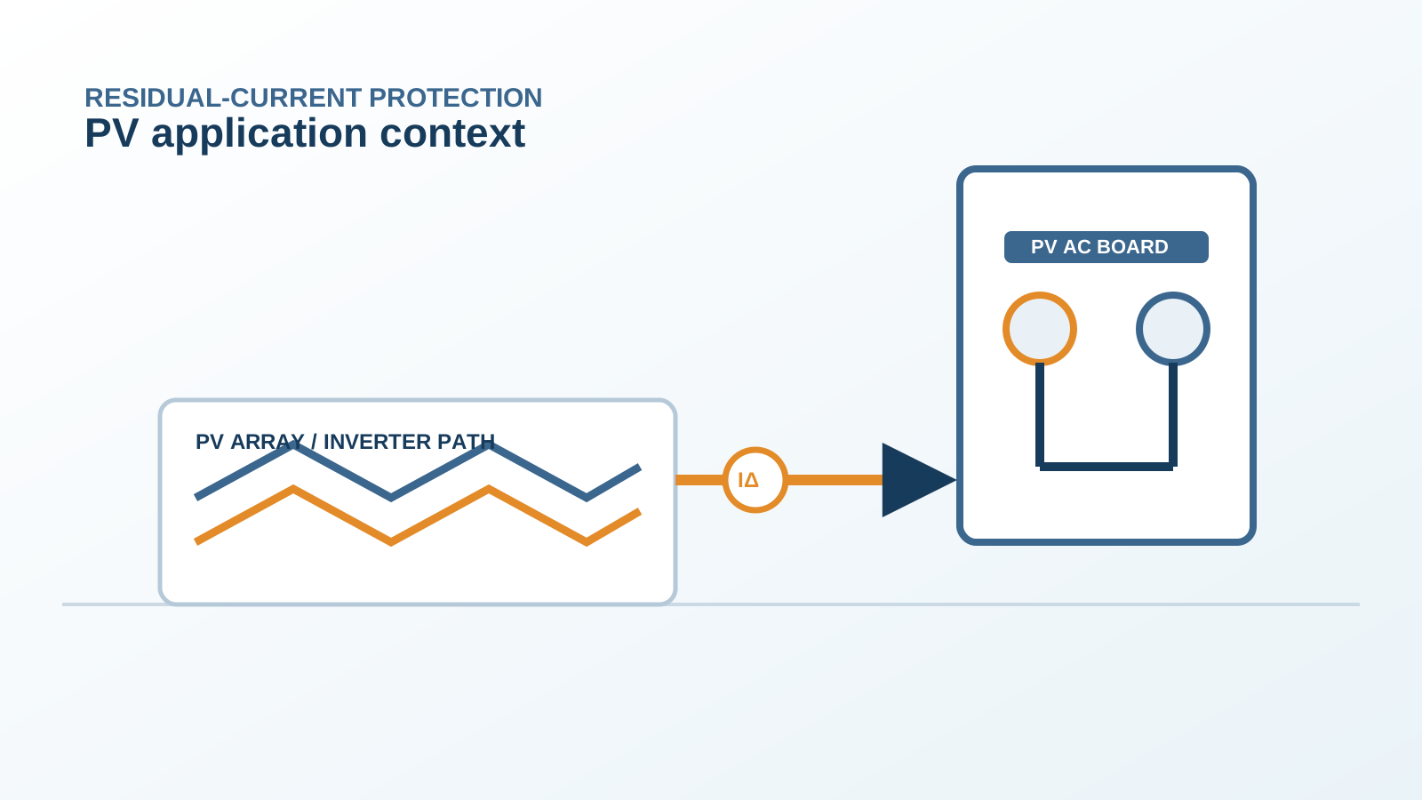
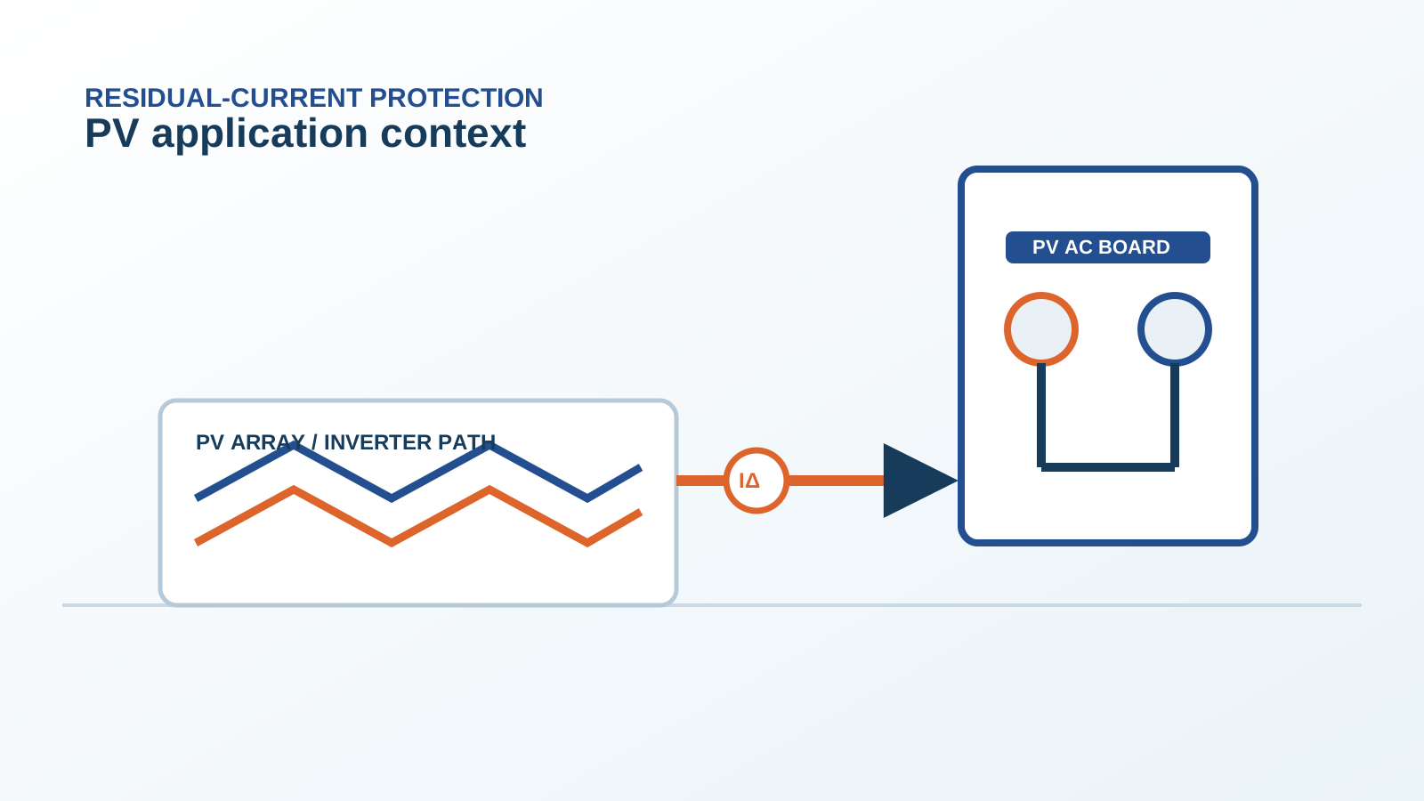
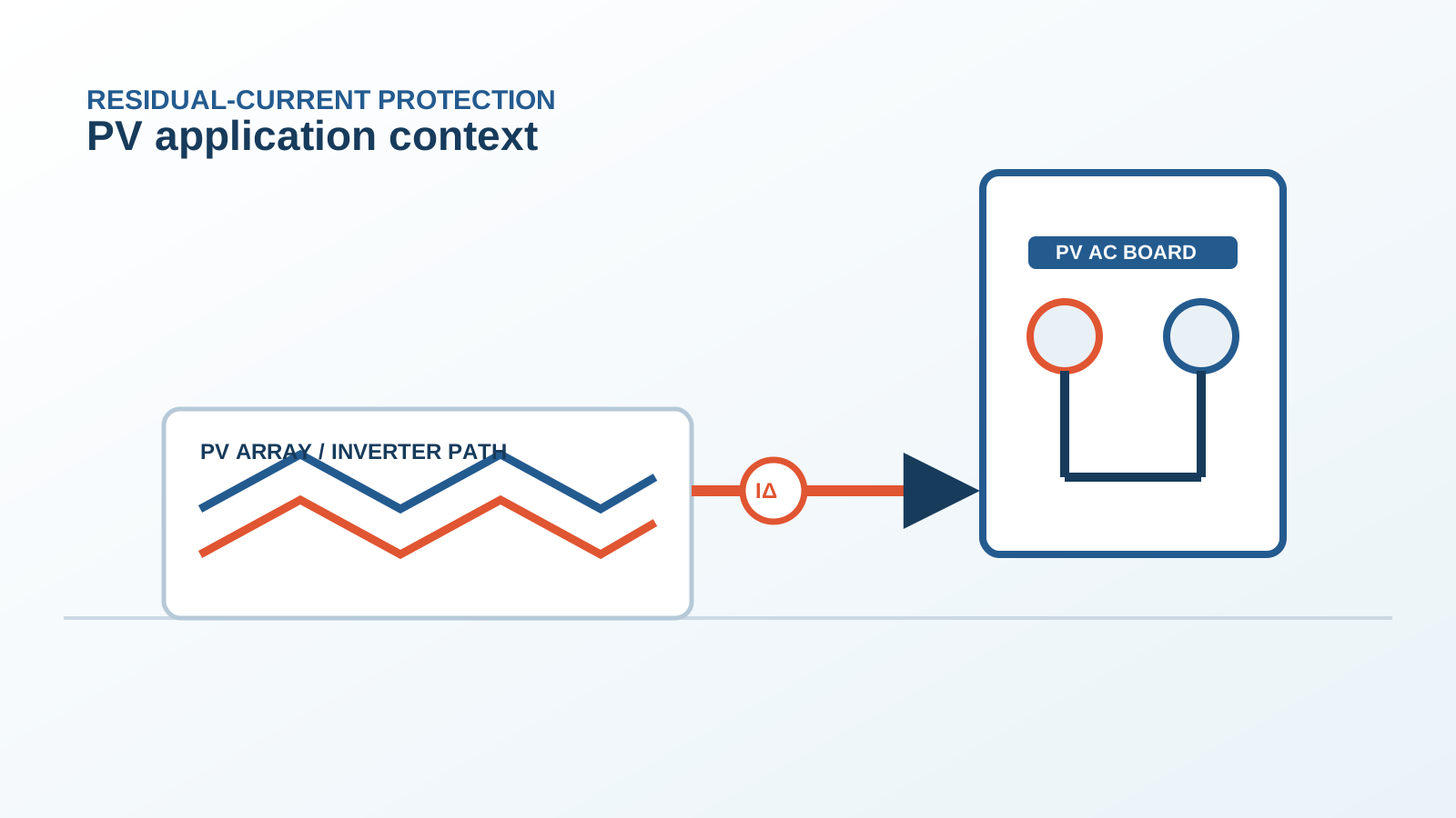
A neutral-ground loop forms when the neutral and protective-earth conductors are bonded at more than one point, creating a closed path. In a PV AC board this can happen through the inverter, the grid supply and local earthing all tied together.
Technical diagram shown at a readable responsive scale.
2. How it creates stray current
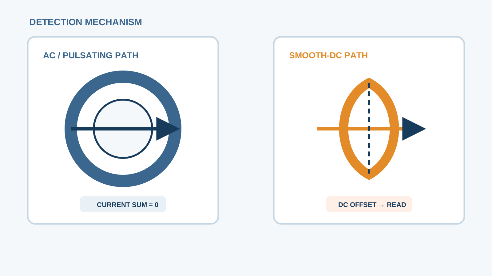
Within that loop, small potential differences drive a stray current that circulates between neutral and earth. Because the RCD sums the currents in its protected circuit, this loop current appears as residual current.
3. RCBO sees it as a fault
An RCBO measures the difference between live and neutral currents. A neutral-ground loop returns part of the current through earth instead of neutral, so the difference is non-zero and the device reads it as a fault, then trips.
4. Multiple earthing points
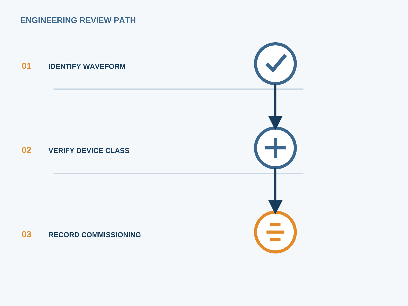
Several earth bonds, inverter frame, board enclosure, grid electrode, supplementary electrode, multiply the loop paths. Each extra bond adds a route for stray current and raises the chance of a spurious trip.
5. Inverter and grid earthing
The inverter and the grid supply each bring their own earthing reference. If both connect to the board neutral or earth at different points, the loop closes through the building. Correct separation of functional and protective earthing prevents this.
6. Finding the loop
Break the neutral-earth bond at one end and measure for continuity between neutral and earth elsewhere; a closed loop shows as a low-resistance path. A residual-current clamp on the earth conductor during load reveals the circulating current.
7. Fixing without losing protection
Remove the redundant neutral-earth bond, keep a single defined earthing point, and separate functional from protective earth. The protective function stays intact while the stray loop current disappears, so the RCBO stops tripping.
8. Acceptance test
After the fix, verify with the RCD test button, confirm no neutral-earth loop with a continuity check, and log residual current under load to show it stays near zero. NEUTRON low-voltage switchgear and DC protection are arranged to keep a single, clean earthing point.
This is general application guidance. Confirm final ratings, trip settings, standards, inverter instructions and local installation requirements against approved project documentation and a qualified engineer's review.
Bring the protection inputs to the first review.
After the fix, verify with the RCD test button, confirm no neutral-earth loop with a continuity check, and log residual current under load to show it stays near zero. NEUTRON low-voltage switchgear and DC protection are arranged to keep a single, clean earthing point.
Discuss a project requirementContinue learning
Explore related technical guidance in Electrical Protection.
Published from the approved period 10 source package; technical claims and source wording are retained for review.