
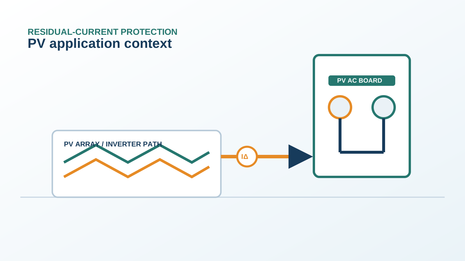
1. Total leakage is the sum of contributors
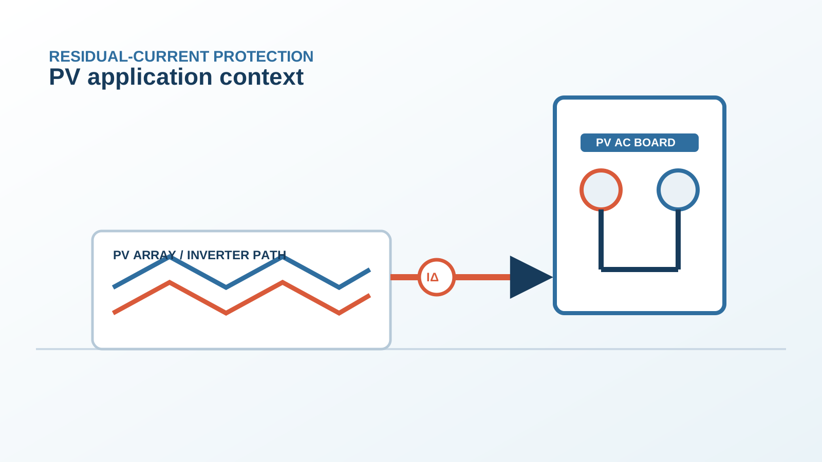
The residual current an RCD sees on a PV system is the vector sum of several small currents: module capacitance, surface leakage, inverter switching and earthing imbalance. None alone may be large, but together they can reach the trip threshold.
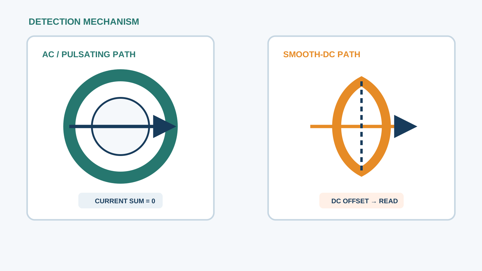
Technical diagram shown at a readable responsive scale.
2. Module capacitance
Each module contributes stray capacitance between its cells and frame. Over hundreds of panels this becomes micro-farads of coupling to earth, the main driver of capacitive leakage especially during voltage changes.
3. Soiling and humidity
Dust, pollen and salt on the front glass or frame create weak conductive films. When humidity rises these films carry surface leakage that adds to the capacitive component and is largest on soiled or coastal arrays.
4. Inverter switching
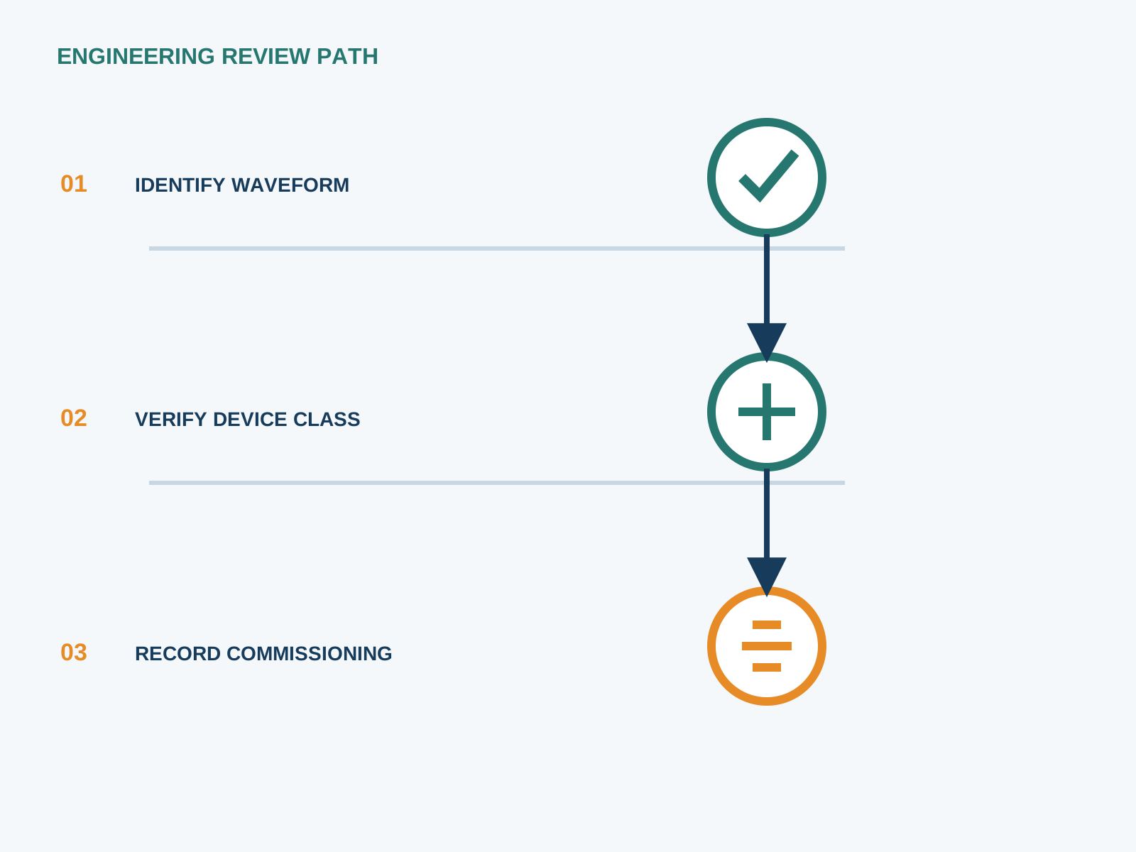
The inverter high-frequency switching injects mixed-frequency common-mode current through the array stray capacitance. This is the same EMI path that can disturb an unfiltered RCD and adds to the total residual reading.
5. Earthing method
The chosen earthing scheme sets how much common-mode voltage appears and therefore how much leakage flows. A floating array with insulation monitoring behaves differently from a solidly earthed array; the RCD sees the result of that choice.
6. Measuring total leakage
Measure the total residual with a clamp meter on the protective conductor under normal operation and during the morning ramp. Logging over a week shows the daily peak and whether it trends toward the threshold.
7. Keeping below the trip
Keep the leakage budget under the trip level by clean modules, correct earthing, screened DC routing and a correctly set inverter monitor. The aim is headroom so genuine faults still trip while normal leakage does not.
8. Design checklist
Sum the expected contributors for the array size and site, pick an all-current-sensitive device with margin, verify the earthing scheme, and confirm the inverter monitor setting. NEUTRON DC protection and switchgear are specified to fit this leakage budget.
This is general application guidance. Confirm final ratings, trip settings, standards, inverter instructions and local installation requirements against approved project documentation and a qualified engineer's review.
Bring the protection inputs to the first review.
Sum the expected contributors for the array size and site, pick an all-current-sensitive device with margin, verify the earthing scheme, and confirm the inverter monitor setting. NEUTRON DC protection and switchgear are specified to fit this leakage budget.
Discuss a project requirementContinue learning
Explore related technical guidance in Electrical Protection.
Published from the approved period 10 source package; technical claims and source wording are retained for review.