
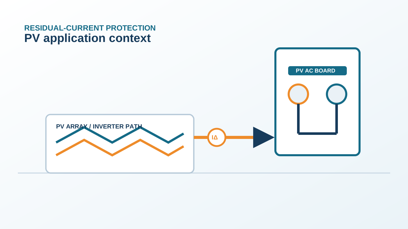
1. Common-mode EMI from inverters
A transformerless PV inverter switches DC to AC at high frequency, generating a common-mode voltage between the array and earth. This high-frequency voltage drives a small common-mode current through the array stray capacitance and any conductive path back to the grid.
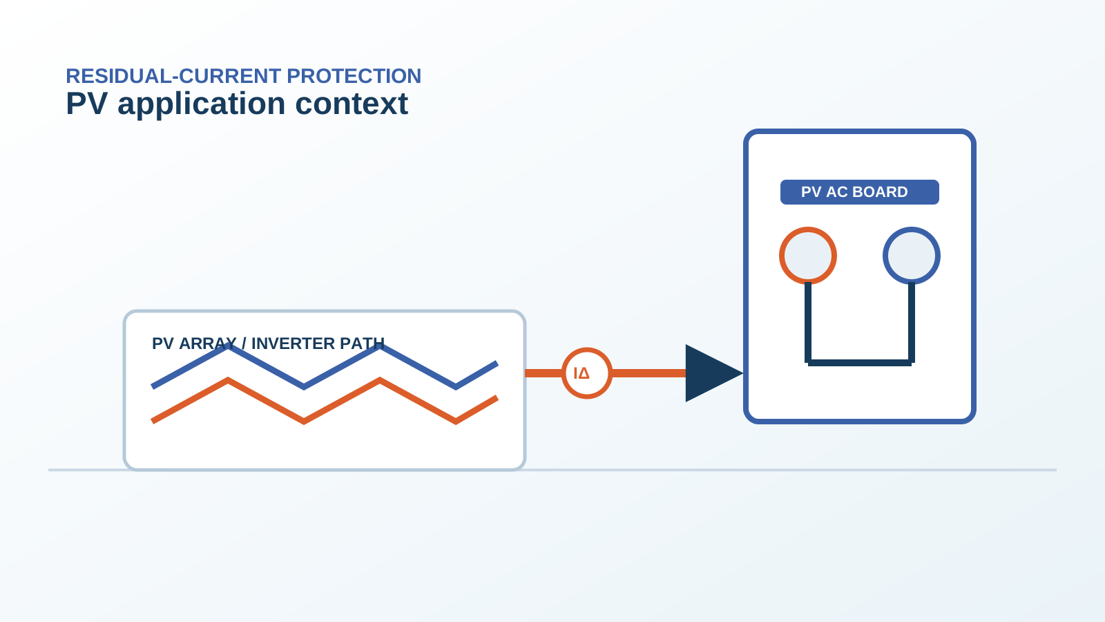
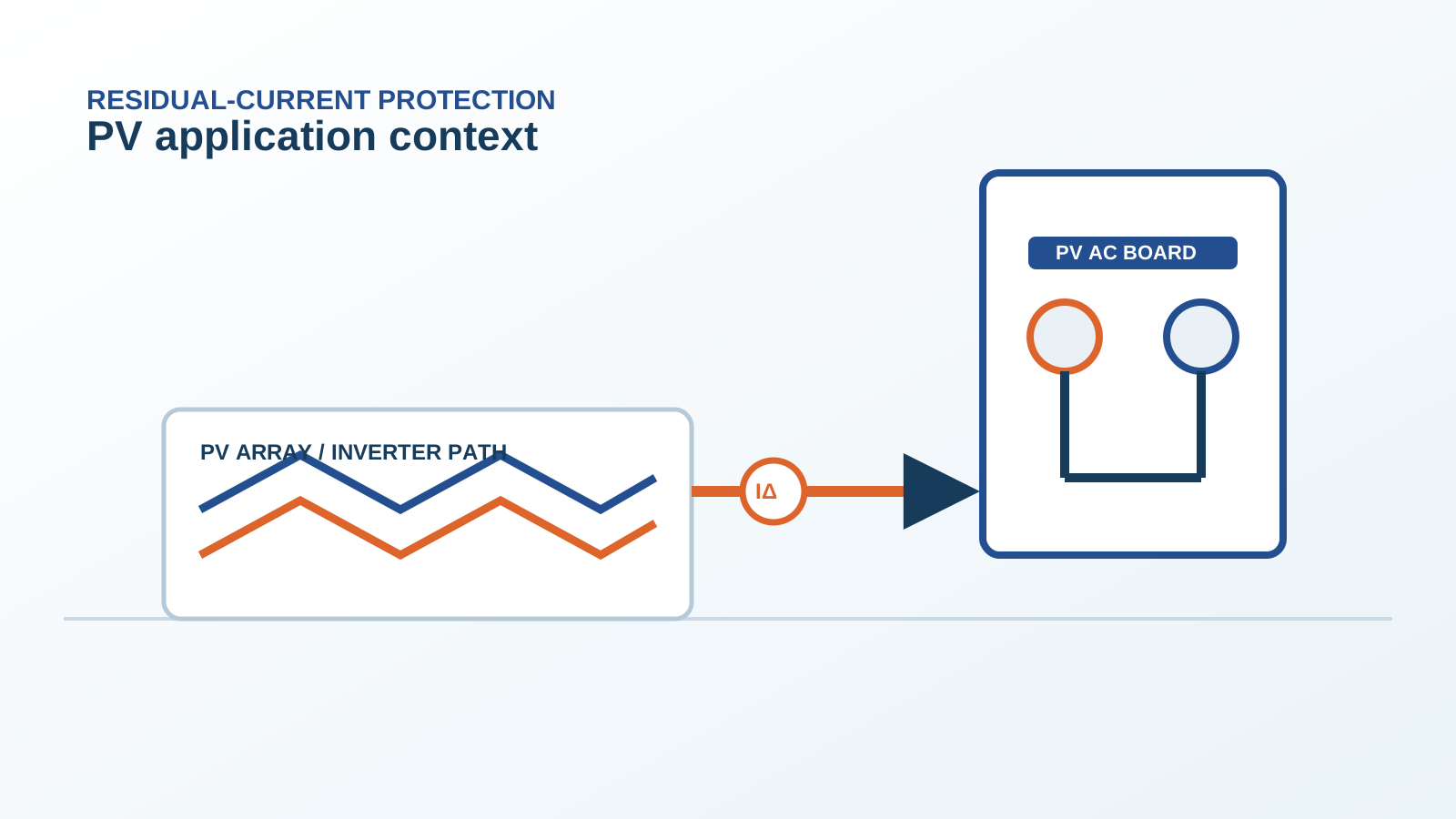
Technical diagram shown at a readable responsive scale.
2. How EMI couples into the RCD
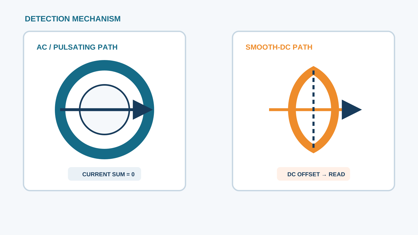
The common-mode current returns through the protective-earth conductor and the RCD sensing path. If the RCD sensing electronics are not filtered for high-frequency content, the differential measurement can be disturbed, producing a spurious residual reading the device interprets as a fault.
3. Filter and grounding effect
A properly installed EMI filter at the inverter and a clean, low-impedance protective-earth connection reduce the common-mode current reaching the board. Poor or long earth leads raise the impedance and let more high-frequency current circulate through the RCD.
4. RCD front-end immunity
Some residual-current devices include filtering and a frequency-dependent trip characteristic that ignores short high-frequency bursts. All-current-sensitive Type B devices are generally more tolerant of the mixed-frequency leakage present in PV AC boards than basic Type A units.
5. Cable routing and separation
Keep the DC array cables and the AC output cables separated, and route the protective-earth conductor with the phase conductors. Cross-coupling between circuits is reduced when cables run in their own trays with adequate spacing.
6. Measurement with a current probe
A wideband current probe or residual-current clamp on the protective-earth conductor shows the high-frequency content. Comparing the spectrum with the RCD trip time confirms whether EMI, not a fault, is the trigger.
7. Fixes that keep protection
Fixes should remove the coupling, not disable the device. Improve the earth bond, add or reseat the inverter filter, re-route cables, and confirm the RCD type. Never defeat the protective function to stop a nuisance trip.
8. Commissioning checks
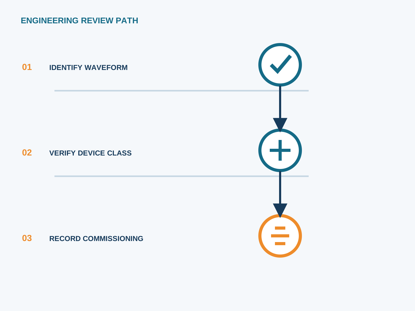
During commissioning, record residual current across the morning ramp and under full load, verify the earth-bond resistance, and confirm the RCD trip characteristic against its marked immunity. NEUTRON DC protection and switchgear are selected to sit within this coordinated layout.
This is general application guidance. Confirm final ratings, trip settings, standards, inverter instructions and local installation requirements against approved project documentation and a qualified engineer's review.
Bring the protection inputs to the first review.
During commissioning, record residual current across the morning ramp and under full load, verify the earth-bond resistance, and confirm the RCD trip characteristic against its marked immunity. NEUTRON DC protection and switchgear are selected to sit within this coordinated layout.
Discuss a project requirementContinue learning
Explore related technical guidance in Electrical Protection.
Published from the approved period 10 source package; technical claims and source wording are retained for review.