
1. What parasitic capacitance is in PV
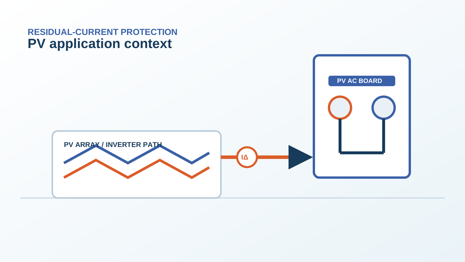
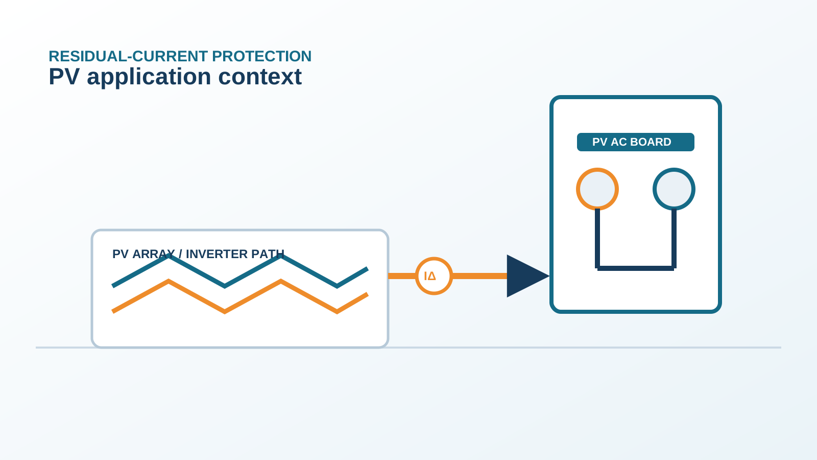
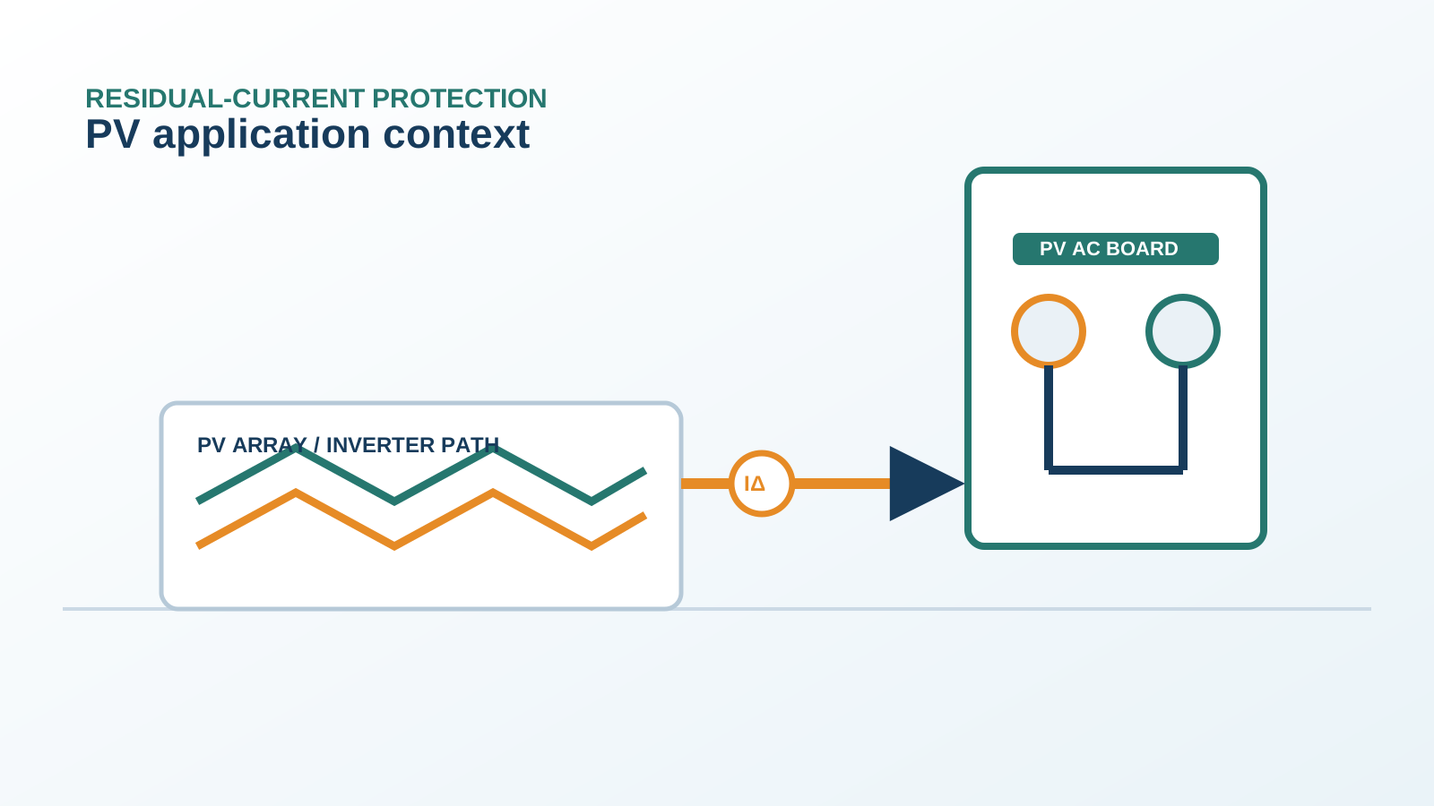
A photovoltaic module is a laminated sandwich of semiconductor cells between glass and a polymer backsheet. Between the live DC conductors and the grounded frame a thin dielectric layer forms a parasitic (stray) capacitance, typically a few nano-farads per square meter of panel area. Across a large array this sums into micro-farads, creating a measurable capacitive coupling path to earth.
Technical diagram shown at a readable responsive scale.
2. Why leakage peaks in the morning
At sunrise the array voltage rises from zero to operating level while dew still coats the surface. The changing voltage across the parasitic capacitance drives a displacement current I = C x dV/dt. The steepest dV/dt occurs during the early ramp, so the capacitive leakage is largest in the first minutes after the inverter starts, exactly when many nuisance trips are reported.
3. Capacitive current versus fault current
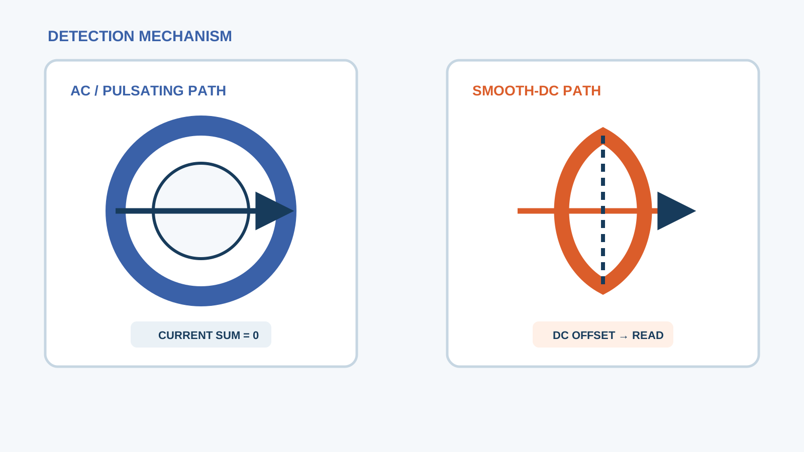
A healthy capacitive current is symmetric and predictable; a true earth fault is a resistive path that persists. An RCD cannot tell them apart by nature, it only measures the net residual current. When the capacitive component plus normal operating leakage exceeds the trip threshold, the device opens even though no dangerous fault exists.
4. RCD sensitivity versus array capacitance
A 30 mA RCD on a large array can see several milliamps of pure capacitive leakage before any fault. Where total array capacitance is high, the steady-state displacement current alone eats into the tripping margin, leaving little headroom for genuine faults or for the morning peak.
5. Mitigation through screening and earthing
Installers reduce the effect by screening the DC wiring, keeping conductors close, and by choosing an earthing scheme that limits the common-mode voltage swing. A well-planned cable route lowers the effective capacitance seen by the protective device.
6. Inverter compensation
Many transformerless inverters include an internal residual-current monitor that intentionally tolerates the expected capacitive leakage and disconnects only on a true fault. Correct commissioning of that internal monitor, together with an externally rated Type B device, keeps the morning peak from causing a full board trip. The inverter is supplied by others; NEUTRON supplies the DC protection and low-voltage switchgear that coordinate with it.
7. Measurement on site
Measure the residual current with a clamp-type residual-current meter on the array output before the RCD, under the morning ramp, to capture the peak. Logging over several days shows whether the trip coincides with the voltage ramp rather than a fault event.
8. Design rules
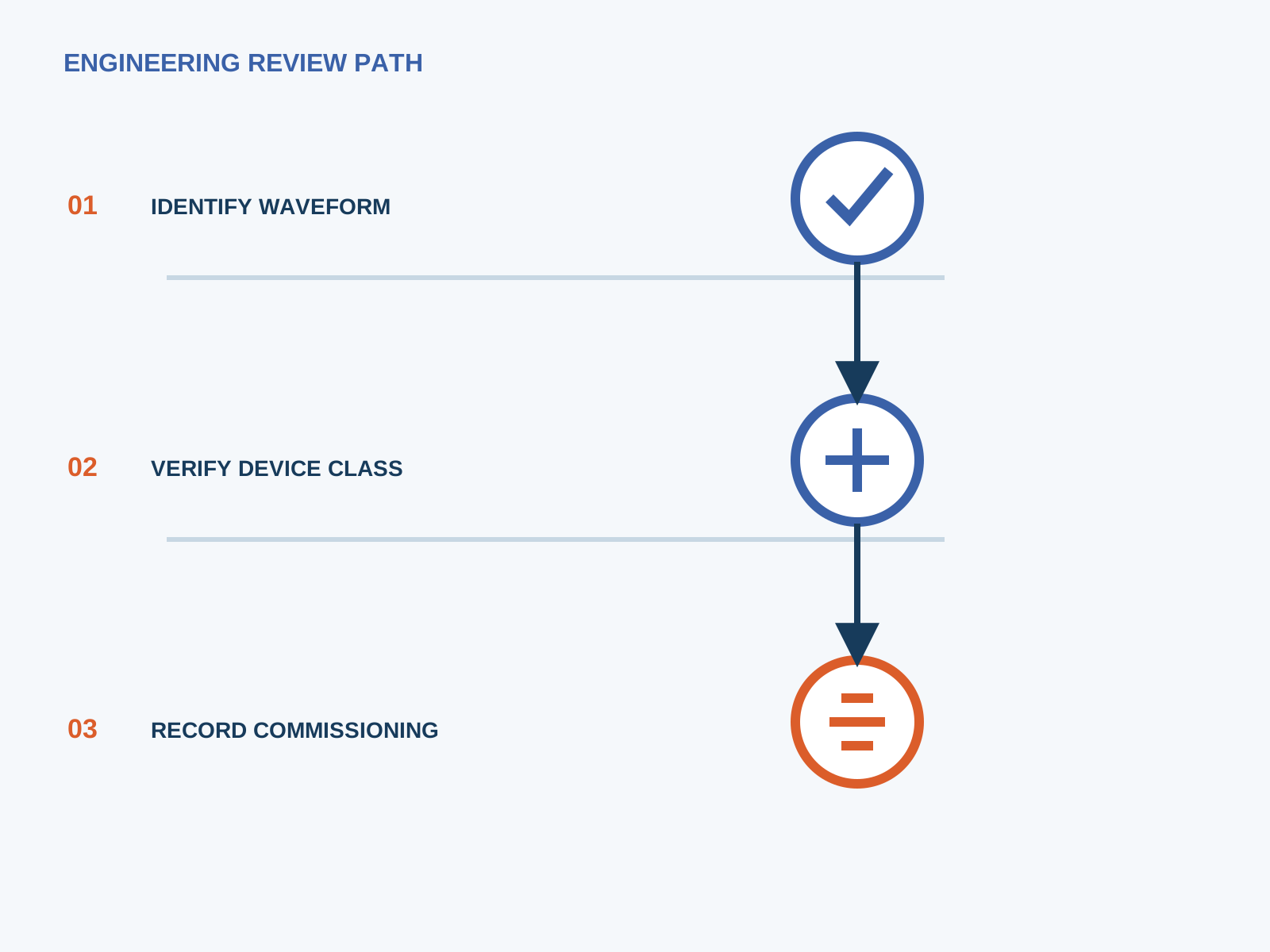
Size the protective concept for the worst-case array capacitance, not the nameplate. Keep DC conductor runs short and separated from earth, verify the inverter internal monitor setting, and select an all-current-sensitive device rated for smooth DC. NEUTRON supplies the DC protection and low-voltage switchgear that match these rules.
This is general application guidance. Confirm final ratings, trip settings, standards, inverter instructions and local installation requirements against approved project documentation and a qualified engineer's review.
Frequently asked questions
Why does my RCD trip in the morning?
The array voltage ramps up at sunrise while dew is present, driving a capacitive displacement current through the module stray capacitance to earth. The peak dV/dt sits in the first minutes after start, pushing residual current above the trip threshold even with no fault.
Is parasitic capacitance a fault?
No. It is a normal electrical property of any insulated conductor near earth. It only becomes a problem when the summed capacitive leakage, added to operating leakage, reaches the RCD threshold.
Bring the protection inputs to the first review.
Size the protective concept for the worst-case array capacitance, not the nameplate. Keep DC conductor runs short and separated from earth, verify the inverter internal monitor setting, and select an all-current-sensitive device rated for smooth DC. NEUTRON supplies the DC protection and low-voltage switchgear that match these rules.
Discuss a project requirementContinue learning
Explore related technical guidance in Electrical Protection.
Published from the approved period 10 source package; technical claims and source wording are retained for review.